7
Insert hose assembly through bottom of the crimper
base plate up through die fingers.
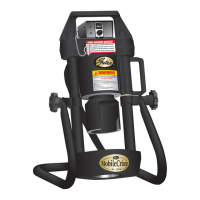
Locate top of ferrule or MegaCrimp
®
coupling approximately 1/8” below top of the die
fingers. Place die cone over the die fingers to hold
assembly in position.
Move die cone and backup ring back against BOTH
rear locating pins of crimp
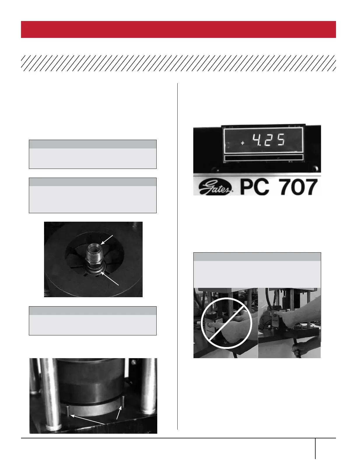
The crimp data manual gives approximate
digital readout setting for specific hose/coupling
combination. Rotating the knob on top of switch box
clockwise will increase the setting; counterclockwise
will decrease the setting.
Turn knob to a setting below the desired setting.
Then turn knob back up to the desired setting.
(Digital readout numbers may jump a number, e.g.,
5.50 to 5.49 or 5.51. This will not affect crimp
diameter of the coupling.)
Activate pump by pressing and holding the crimp
switch on switch box. The readout light will go out
when the crimp switch is pushed in. When actuator
rod contacts switch box’s microswitch, the power to
pump is automatically turned off.
Rear
locating pins
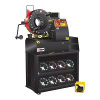
Keep hand out from under ram
at all times.
WARNING:
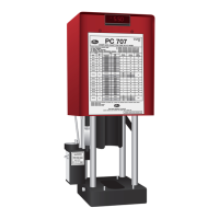
Be sure the hex of a straight stem or round
portion of a bent tube rests against ferrule.
IMPORTANT:
Do not use 720, 737, or 739 die sets
with optional notched die cone. May cause
damage to die cone.
CAUTION:
Always wear safety glasses and
KEEP HANDS AWAY
FROM MOVING PARTS.
CAUTION:
Incorrect Correct
Top of
Die Finger
Top of
Ferrule
OPERATING INSTRUCTIONS (continued)
PC 707 CRIMPER SAFETY AND OPERATING MANUAL
7.
8.
9.
10.
11.
12.