23CyScan Positioning System • Installation and Maintenance Guide r1.1
GC S
GC S
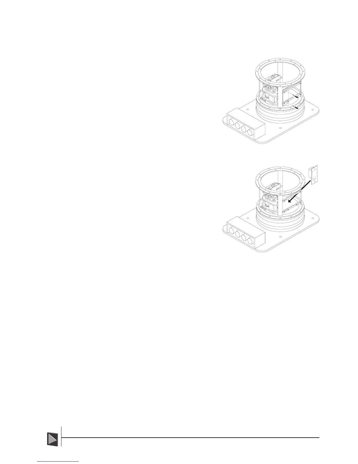
Stage 7 - The Yaw Gyro
To remove the Yaw Gyro:
1 Looking from the Starboard side of
the sensor locate the yaw gyro - a
small vertically mounted circuit
board. Using a 2.5mm A/F hex tool
to remove the two M3 x 16 screws
that secure the yaw gyro board to
the sensor frame (these are
normally hidden behind the
controller board).
2 Disconnect the ribbon cable
connector from the yaw gyro
board.
3 Lift out the yaw gyro unit.
To fit the Yaw Gyro:
1 Place the yaw gyro board into the
sensor frame adjacent to the pitch
actuator. The large rectangular
component (the gyro unit) should
be uppermost on the board.
2 Locate the ribbon cable leading
from the VRU board and attach it
to the connector situated towards
the bottom of the yaw gyro
assembly.
3 Insert two M3 x 16 screws through
the upper and lower frame bars
and into the corresponding
threaded holes of the yaw gyro
board. Using a 2.5mm A/F hex
tool, tighten both screws to
reasonable hand tightness.