32CyScan Positioning System • Installation and Maintenance Guide r1.1
GC S
GC S
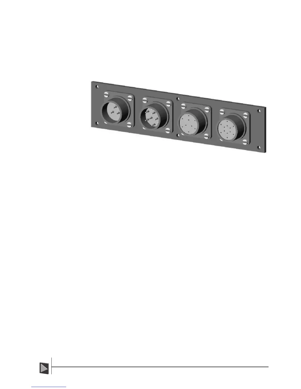
Appendix 1 - CyScan Sensor Connector Pin-outs
The CyScan sensor has four connectors situated at the Stern end of its base plate. Three
of the connectors are used during operation, the fourth is used (offline) when the leveller
component requires a software upgrade.
The pin-outs of the four connectors are given here for completeness.
DC Power
Pin Signal
A 24VDC 6A
B0V
C Earth
DP Feed
Pin Signal
A0V
B RXA
C TXB
D TXA
E RXB
F 24V
GNC
H GND
JNC
Console
Pin Signal
A0V
B RXA
C TXB
D TXA
E RXB
F 24V
GNC
H GND
JNC
IMPORTANT: 0V is not the same as
GND. 0V is the power supply return
whereas GND is a digital ground
connection for the communication
ports. If 0V and GND are crossed or
joined, the system will not function.
Leveller Programming
Pin Signal
A DSR
B RXD
CNC
D TXD
E CTS
FNC
GNC
H GND
J VPPEN
KNC
LNC
MNC
Appendices
DC Power
3 way plug
DP Feed
9 way plug
Console
9 way socket
Leveller
Programming
12 way socket