48CyScan Positioning System • Installation and Maintenance Guide r1.1
GC S
GC S
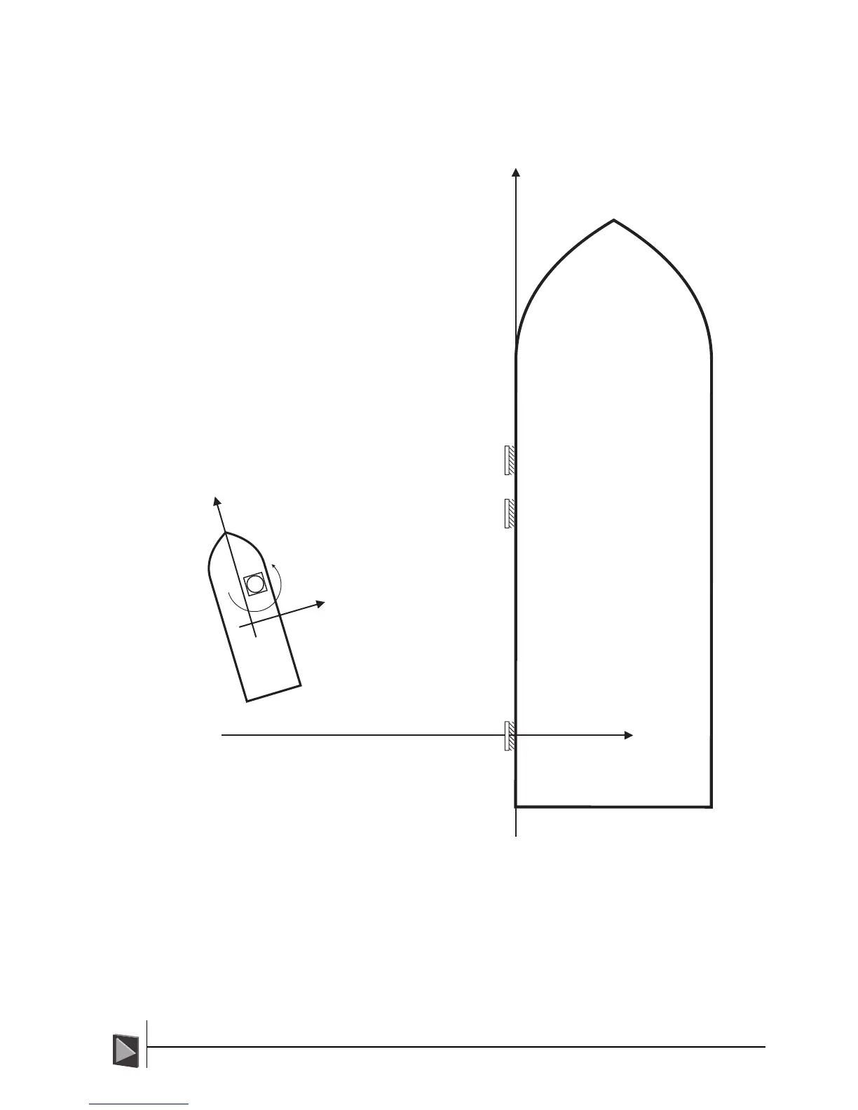
Reflector Positioning Examples
These three pages provide examples of typical reflector layouts.
Example 1 - Ship on Tankers Port side, CyScan on ships Starboard side
B
1
2
3
A
Reflector Positions
1 A=0, B=0, orientation= 270
0
2
3
A=+52.52m, B=0, orientation= 270
A=+64.89m, B=0, orientation= 270
0
0
CyScan's Position
(NMEA-$RLS convention)
A =
B
+29.559m
= -61.451m
Heading = 345
0
Notes:
1 The DP system will display the Origin of the A and B axes. This could be any
point on the tanker, the main mast, midway between perpendiculars or one of
the reflectors. In this example it is number 1 reflector.
2 The reflector numbering should be chosen so that they form an anti-clockwise
sequence when seen by CyScan.
This can be 1-2-3, or 2-3-1 or 3-1-2, etc.
3 In Auto Survey, target 1 would be the datum (primary target) and denotes the
origin of A/B frame.