49CyScan Positioning System • Installation and Maintenance Guide r1.1
GC S
GC S
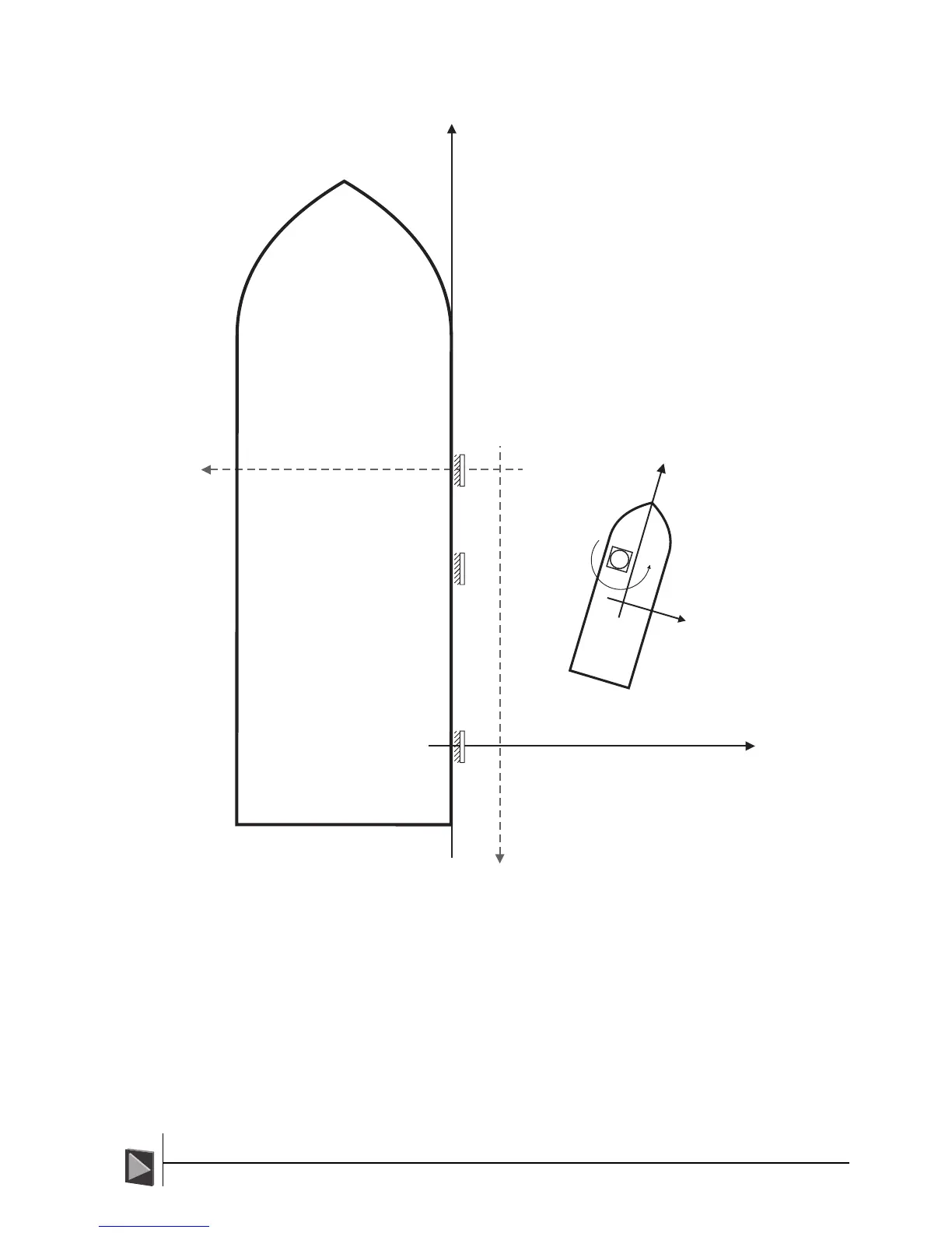
Example 2 - Ship on Tankers Starboard side, CyScan on ships Port side
Notes:
1 The DP system will display the Origin of the A and B axes. This could be any
point on the tanker, the main mast, midway between perpendiculars or one of
the reflectors. In this example it is number 1 reflector.
2 The reflector numbering should be chosen so that they form an anti-clockwise
sequence when seen by CyScan.
This can be 1-2-3, or 2-3-1 or 3-1-2, etc.
3 An auto-survey would have assigned reflector 2 as the origin resulting in the A/
B frame pointing downwards and left respectively, i.e. target 2 would be
labelled as 1, target 3 as 2 and target 1 as 3. In terms of navigation the result-
ing ship’s position in this auto-surveyed frame would still be a positive A coordi-
nate but a negative B coordinate.
B
B*
1
3
2(1*)
(2*)
(3*)
A
A*
Reflector Positions
1 A=0, B=0, orientation=+90
0
2
3
A=+56.21m, B=0, orientation=+90
A=+42.51m, B=0, orientation=+90
0
0
* When auto-surveyed (Items shown in grey)
1
2
3
Specifically, the auto-surveyed reflector positions
would be:
A=0, B=0, orientation=+270
A=13.7m, B=0, orientation=+270
A=56.21m, B=0, orientation=+270
0
0
0
Resulting in a CyScan navigation position of:
(NMEA-$RLS convention)
+15.028m
= -38.251m
Heading = 195
0
A =
B
CyScan's Position
(NMEA-$RLS convention)
A =
B
+41.182m
= +38.254m
Heading = +15
0