47CyScan Positioning System • Installation and Maintenance Guide r1.1
GC S
GC S
Defining Reflector Positions
To achieve the most accurate results, please follow the suggestions given below when
defining the coordinates of installed reflectors.
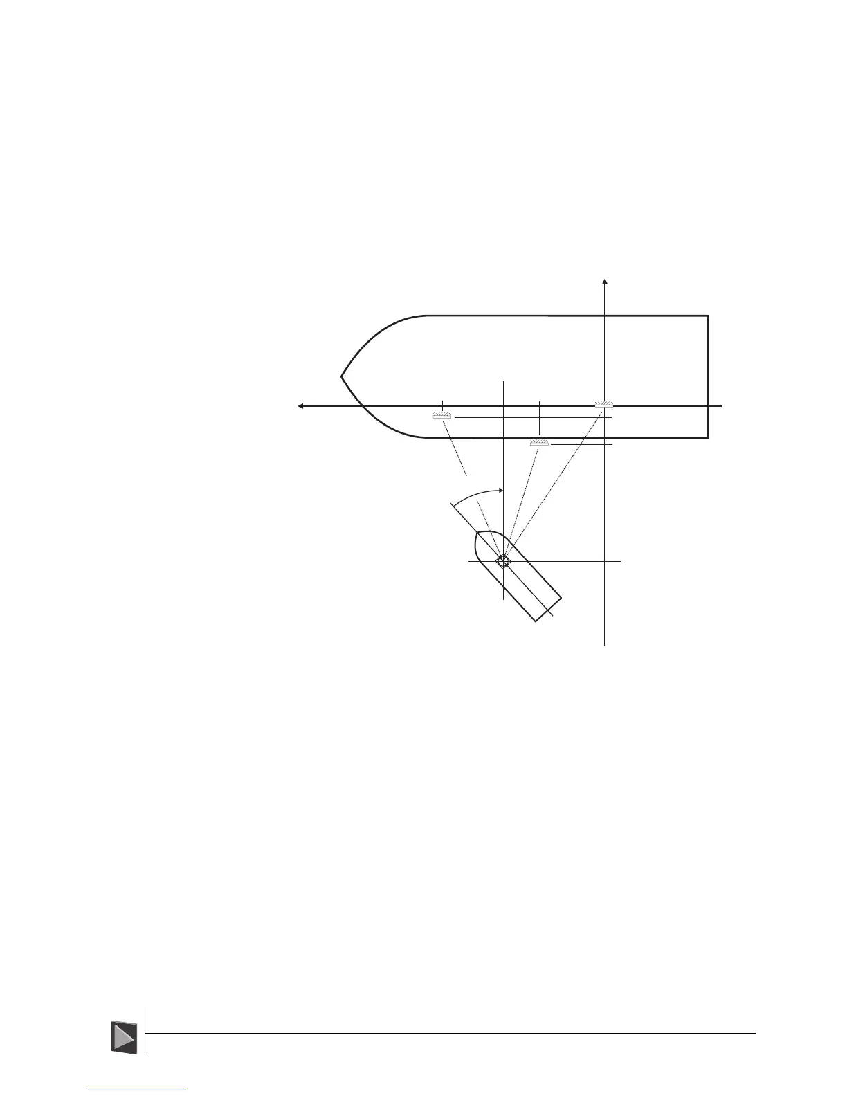
• Target positions are measured using two perpendicular axes, A and B. The Origin
of the two axes can be any fixed point on the Mooring Point/Vessel, with all
measurements along both axes being taken from that point.
If the reflectors are mounted along the side of the Mooring Point/Vessel, then the
logical arrangement (and the most straightforward for measuring reflector posi-
tions) is to make the A and B axes match those of the vessel (as shown below).
This would involve the B axis passing across the vessel (starboard to port, or vice
versa), while the A axis would run parallel to the side of the vessel (stern to bow,
or vice versa).
Defining Reflector Positions
The Origin can be any fixed point on the vessel,
however, in most cases it will be defined as the
first reflector R
1
. The remaining reflectors are
defined relative to the origin using the
perpendicular axes A and B running through it.
• If the Mooring Point/Vessel has no particular fixed reference point, then it is
recommended that the first reflector, R1 is designated as the Origin.
• The reflectors should be numbered starting from the one on the far right (as
viewed from the expected working area) and continuing anticlockwise through the
other reflectors.
• The direction in which each reflector faces must be declared to the CyScan Con-
sole. All measurements are made using the direction of the reflector face relative
to the direction of the A axis. Using a centreline running through the reflector,
perpendicular to the reflector face, the angle between this line and the A axis is
measured and declared to the system.
Using the above diagram as an example, the perpendicular centrelines of all the
reflectors are parallel to the B axis, but pointing in the opposite direction (i.e. they
are facing the sea) – therefore they all have a rotation (or Orientation) of 270
degrees.
• The reflector definitions must be entered in the order R1, R2, R3, etc.
• When using auto-survey the first reflection detected in each rev will be used as the
datum or primary target defining the origin of the A/B coordinate frame.
Please refer to the following three pages for examples of typical reflector layouts.