5–68 850 FEEDER PROTECTION SYSTEM – INSTRUCTION MANUAL
SYSTEM CHAPTER 5: DEVICE, SYSTEM, INPUT AND OUTPUT SETPOINTS
LEA (Low Energy Analog)
The 850-P can be connected to 6 LEA voltage inputs (two 3-phase voltage banks, LEA
Bnk1-J2 and LEA Bnk2-J2).
The LEA voltage inputs setup for the 850-P is shown below:
Path: Setpoints > System > Voltage Sensing > LEA Bnk1-J2
Path: Setpoints > System > Voltage Sensing > Ph LEA Bnk2-J2
Settings Descriptions
LEA BANK NAME
Range: Any combination of 13 alphanumeric characters
Default: LEA Bnk1(2)-J2
Enter the name of the phase voltage from bank J2.
PHASE TERMINAL CONNECTION
Range: ABC, ACB, BAC, BCA, CAB, CBA
Default: ABC
Select the type of phase terminal connection to match the LEA Sensors connected to the
relay.
LEA RATED SECONDARY
Range: 1.0 to 10.0 V in steps of 0.1 V
Default: 10.0 V
Select the output secondary voltage (defined on the voltage sensor) connected to the
LEA inputs.
LEA RATED PHASE ANGLE
Range: 0.0° to 359.9° in steps of 0.1°
Default: 0.0° Lag
Enter the phase shift of secondary voltage related to the primary voltage. Due to the
transformation algorithms used for some sensors, the secondary side keeps a shifted
angle with regards to the primary voltage. The Phase Angle Shift (at nominal system
frequency) information is provided in the sensor data specification sheet. Enter this
information in this setting.
LEA RATIO
Range: 1.00 to 5000.00 in steps of 0.01
Default: 1.00
This setpoint specifies the voltage ratio between the primary and secondary sides for
the desired voltage application.
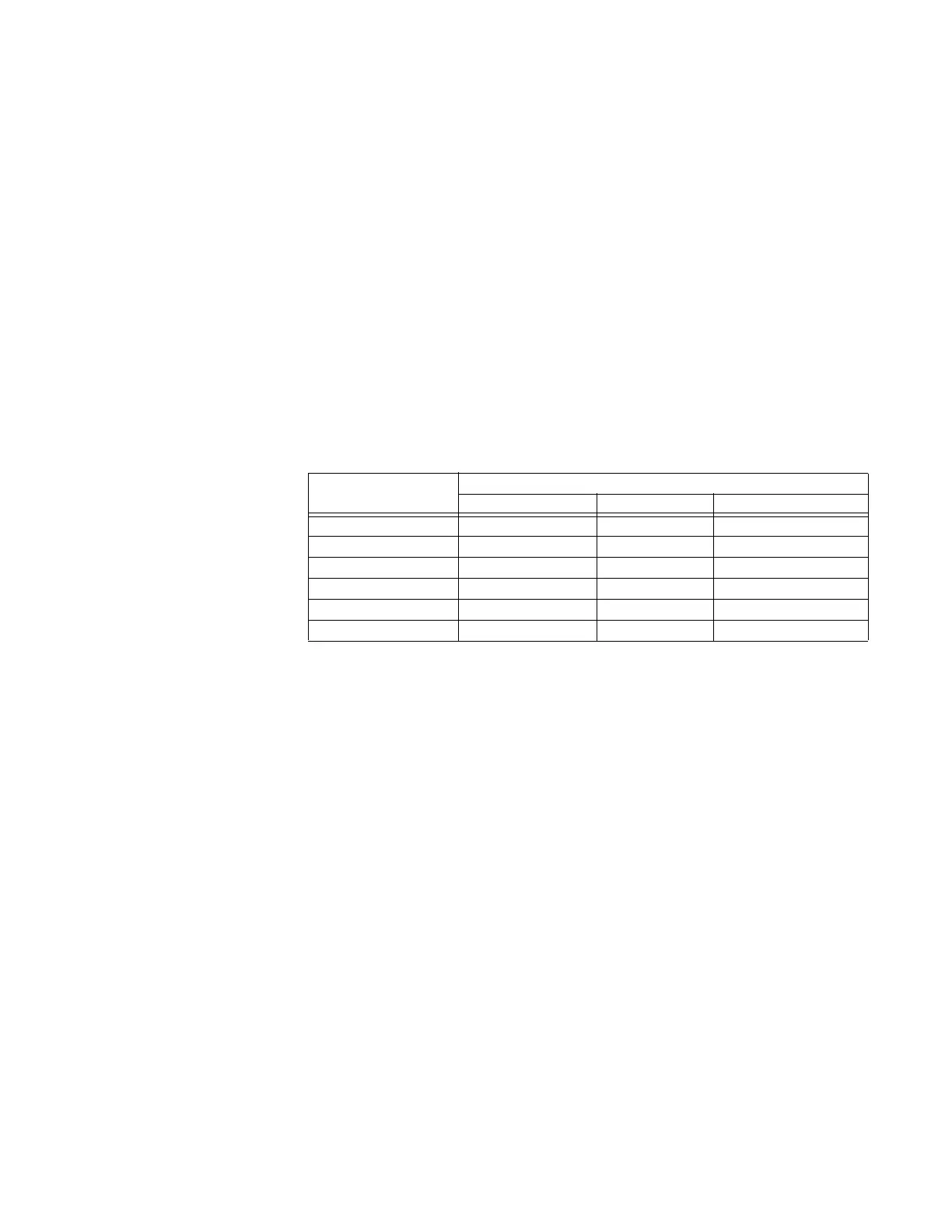
Setting “Phase Terminal
Connection”
Phase Input to the corresponding LEA Sensor terminal input
LEA Sensor 1 LEA Sensor 2 LEA Sensor 3
ABC Phase A Phase B Phase C
ACB Phase A Phase C Phase B
BAC Phase B Phase A Phase C
BCA Phase B Phase C Phase A
CAB Phase C Phase A Phase B
CBA Phase C Phase B Phase A