CHAPTER 6: PROTECTION SETPOINTS VOLTAGE ELEMENTS
850 FEEDER PROTECTION SYSTEM – INSTRUCTION MANUAL 6–105
PICKUP DELAY
Range: 0.000 to 6000.000 s in steps of 0.001 s
Default: 1.000 s
If Inverse Time is selected as an Undervoltage Curve setpoint, the Pickup Delay value is
loaded to variable D in the curve formula. For more information, refer to Undervoltage
Curves.
BLOCK
Range: Off, Any FlexLogic operand
Default: Off
OUTPUT RELAY X
For details see Common Setpoints
.
EVENTS
Range: Enabled, Disabled
Default: Enabled
TARGETS
Range: Disabled, Self-reset, Latched
Default: Self-reset
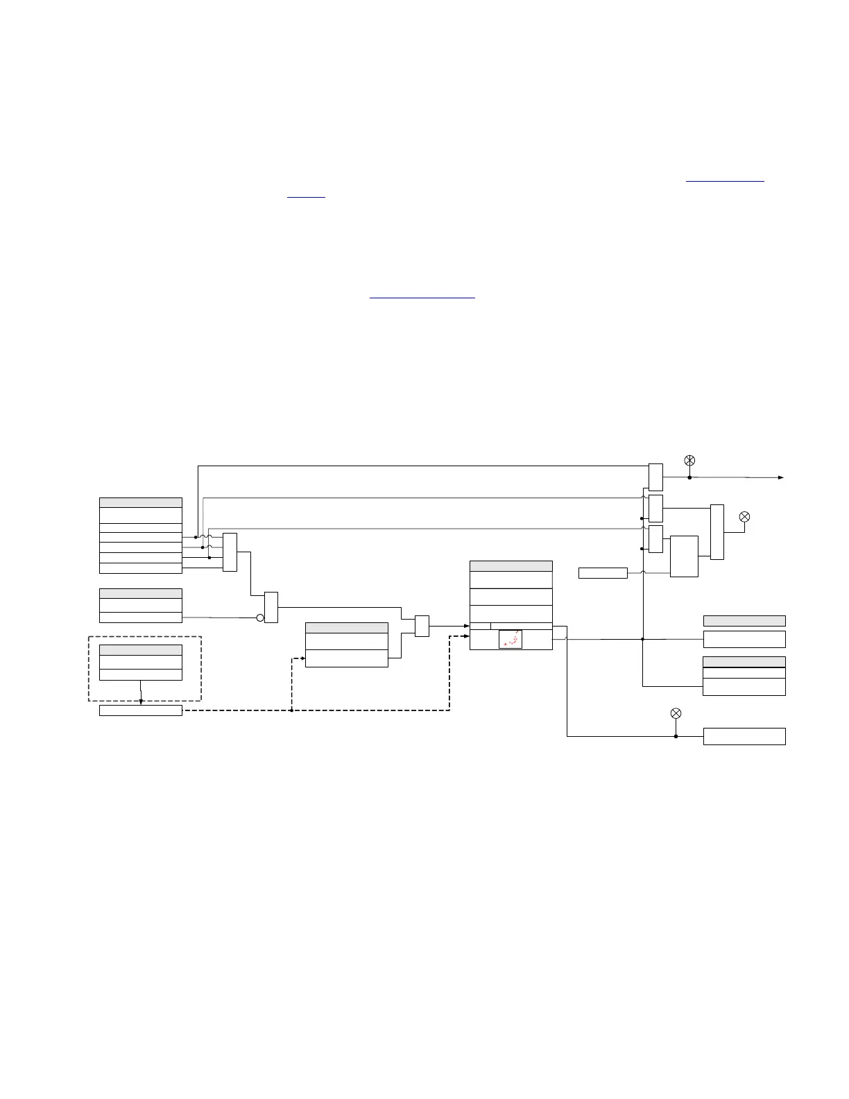
Figure 6-47: Auxiliary Undervoltage Protection logic diagram
894047A3.cdr
SETPOINTS
Auxiliary voltage (Vaux)
SETPOINT
FUNCTION:
Disabled
Trip
PICKUP:
AND
Operate Output Relay 1 (TRIP)
LED: PICKUP
LED: TRIP
Alarm
OR
OR
AND
Latched Alarm
AND
RUN
SETPOINTS
BLOCK :
Off = 0
LED: ALARM /
LATCHED ALARM
RESET
Command
AND
S
R
LATCH
Configurable
FlexLogic Operands
Aux UV 1(2) OP:
Aux UV 1(2) PKP:
PICKUP DELAY:
UNDERVOLTAGE
CURVES:
Vx > PICKUP
SETPOINTS
MINIMUM VOLTAGE:
Vx > MINIMUM
AND
SETPOINTS
Do Not Operate, Operate
OUTPUT RELAYS3 to 7
SETPOINTS
SIGNAL INPUT:
NAME( Ax VT Bnk1-J2
889 only

 Loading...


