EasyManua.ls Logo

GE 850 - Page 464

GE 850
664 pages
To Next Page IconTo Next Page
To Previous Page IconTo Previous Page
Loading...
7–44 850 FEEDER PROTECTION SYSTEM – INSTRUCTION MANUAL
TRANSIENT GROUND FAULT DETECTION CHAPTER 7: MONITORING
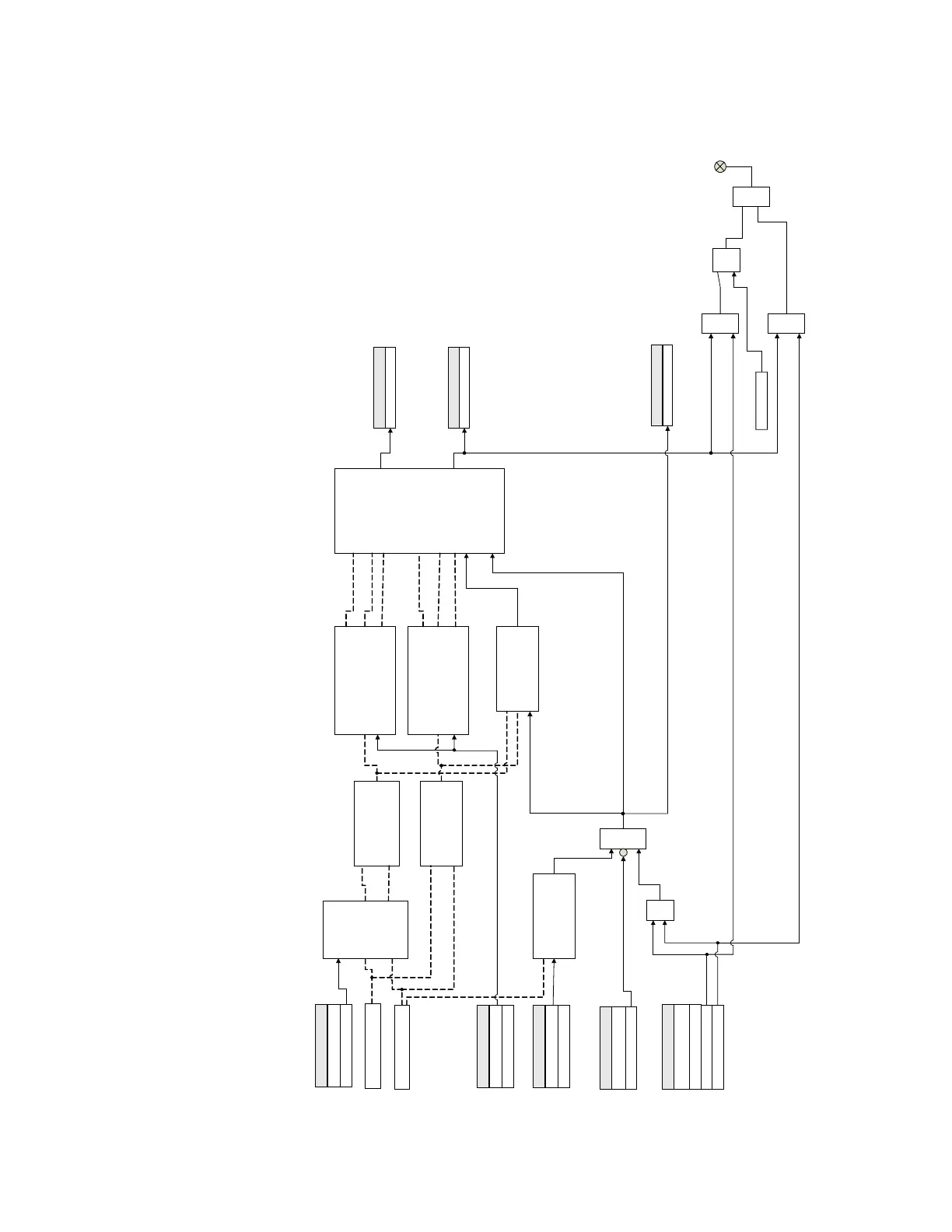
Figure 7-25: Transient Ground Fault Detection logic diagram
Measured: I
N
Measured: V
N
SETPOINT
Frequency :
50 or 60
BandPass Filter
220/264 Hz
Average Transient Q
Average Transient P
Calculate dynamic threshold Q,
max average Q and evaluate
Positive/Negative Q
Calculate dynamic threshold P,
max average P and evaluate
Positive/Negative P
SETPOINT
Power Threshold
Directional Logic
SETPOINT
Residual Voltage Pickup
Activate TGFD
RMS V
N
> Threshold
Select Power P or Q
SETPOINT
BLOCK:
Off = 0
AND
SETPOINT
Function:
Disabled
Latched Alarm
Alarm
OR
LED: ALARM
RESET
Command
S
R
LATCH
TGFD Forward
FlexLogic Operands
TGFD Reverse
FlexLogic Operands
AND
AND
OR
TGFD Start
FlexLogic Operands
894210A1.cdr

Table of Contents

Related product manuals