EasyManuals Logo

GE AF-600 FP Series Design And Installation Guide

GE AF-600 FP Series
121 pages
To Next Page IconTo Next Page
To Previous Page IconTo Previous Page
Page #13 background imageLoading...
Page #13 background image
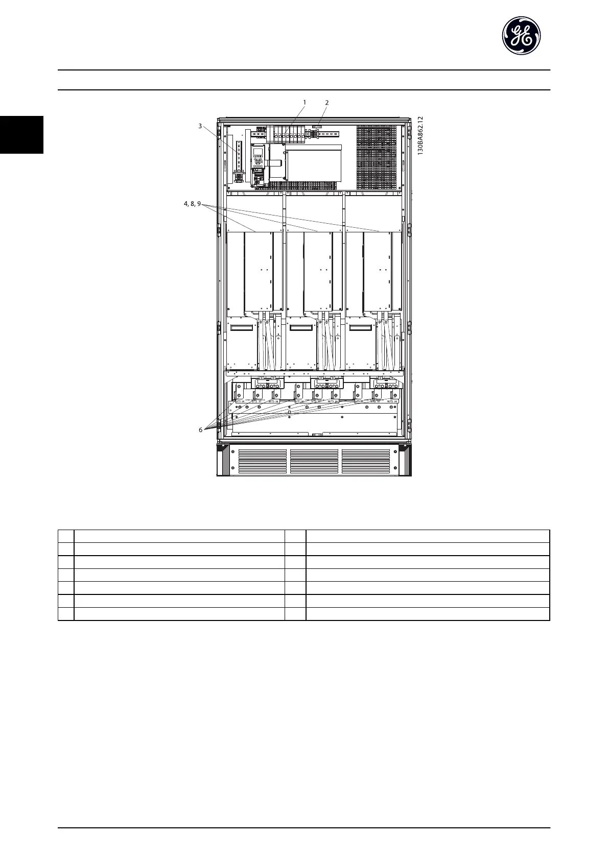
Illustration 1.7 Inverter Cabinet, Unit Sizes 62 and 64
(Unit Sizes 61 and 63 are similar with two inverter modules)
1) External Temperature Monitoring 6) Motor
2) AUX Relay U V W
01 02 03 96 97 98
04 05 06 T1 T2 T3
4) AUX Fan 8) Fan Fuses. See 13.3 Fuse Specifications for part numbers
100 101 102 103 9) SMPS Fuses. See 13.3 Fuse Specifications for part numbers
L1 L2 L1 L2
Table 1.6 Legend to Illustration 1.6
Introduction
AF-600 FP
TM
Design and Installation Guide
10 DET-768b
1
1

Table of Contents

Other manuals for GE AF-600 FP Series

Questions and Answers:

Question and Answer IconNeed help?

Do you have a question about the GE AF-600 FP Series and is the answer not in the manual?

GE AF-600 FP Series Specifications

General IconGeneral
BrandGE
ModelAF-600 FP Series
CategoryI/O Systems
LanguageEnglish

Related product manuals