6.1.3 Frequency Converter Hardware Setup
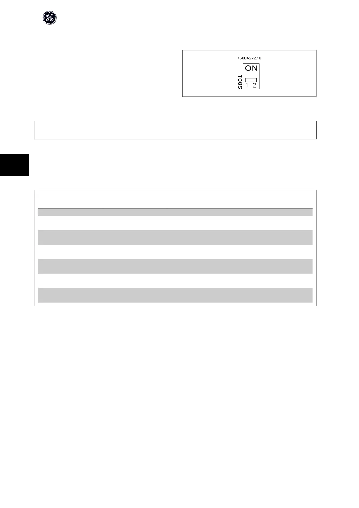
Use the terminator dip switch on the main control board of the frequency
converter to terminate the RS-485 bus.
Terminator Switch Factory Setting
NB!
The factory setting for the dip switch is OFF.
6.1.4 Frequency Converter Parameter Settings for Modbus Communication
The following parameters apply to the RS-485 interface (drive-port):
Parameter
Number
Parameter name Function
O-30 Protocol Select the application protocol to run on the RS-485 interface
O-31 Address Set the node address. Note: The address range depends on the protocol selected
in par. O-30 Protocol
O-32 Baud Rate Set the baud rate. Note: The default baud rate depends on the protocol selected
in par. O-30 Protocol
O-33 PC port parity/Stop bits Set the parity and number of stop bits. Note: The default selection depends on the
protocol selected in par. O-30 Protocol
O-35 Min. response delay Specify a minimum delay time between receiving a request and transmitting a
response. This can be used for overcoming modem turnaround delays.
O-36 Max. response delay Specify a maximum delay time between transmitting a request and receiving a
response.
O-37 Max. inter-char delay Specify a maximum delay time between two received bytes to ensure time-out if
transmission is interrupted.
AF-600 FP Design Guide
106
6

 Loading...


