4.4 Additional Connections
4.4.1 External Fan Supply
Unit size 4x, 5x and 6x
In case the frequency converter is supplied by DC or if the fan must run independently of the power supply, an external power supply can be applied. The connection
is made on the power card.
Terminal No.
Function
100, 101
102, 103
Auxiliary supply S, T
Internal supply S, T
The connector located on the power card provides the connection of line voltage for the cooling fans. The fans are connected from factory to be supplied form
a common AC line (jumpers between 100-102 and 101-103). If external supply is needed, the jumpers are removed and the supply is connected to terminals 100
and 101. A 5 Amp fuse should be used for protection. In UL applications this should be LittleFuse KLK-5 or equivalent.
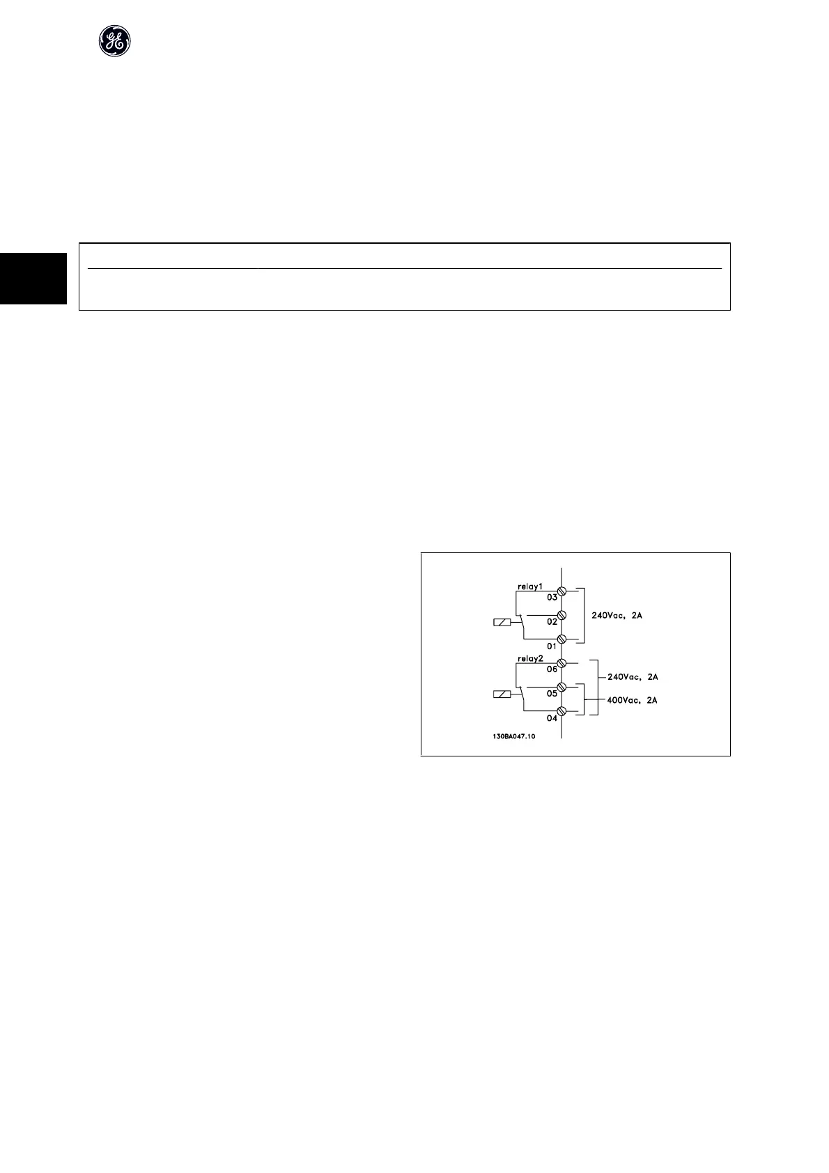
4.4.2 Relay Output
Relay 1
• Terminal 01: common
• Terminal 02: normal open 240 V AC
• Terminal 03: normal closed 240 V AC
Relay 2
• Terminal 04: common
• Terminal 05: normal open 400 V AC
• Terminal 06: normal closed 240 V AC
Relay 1 and relay 2 are programmed in par. E-24 Function Relay, par. E-26 On
Delay, Relay, and par. E-27 Off Delay, Relay.
Additional relay outputs can be added to the drive with the Relay Option
Module, GE Model Number OPCRLY.
AF-600 FP Design Guide
84
4

 Loading...


