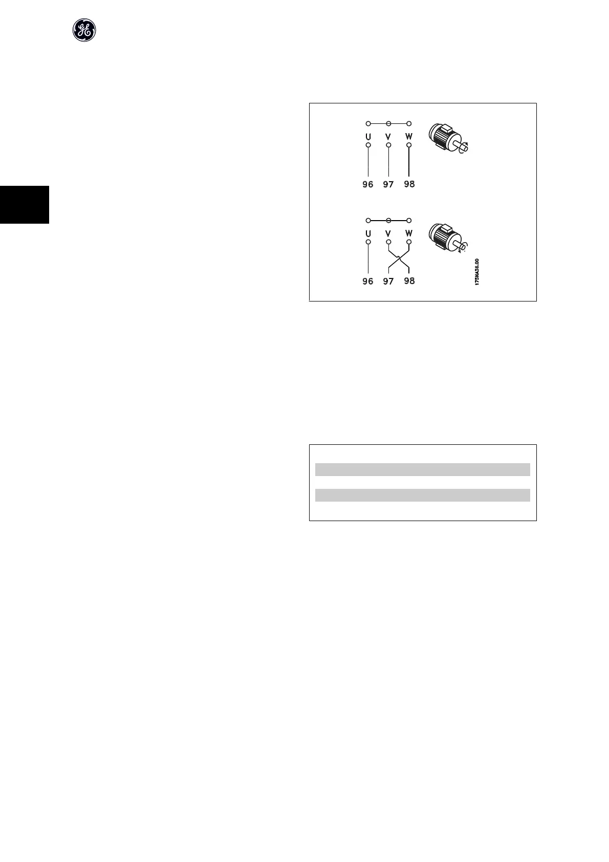
4.4.4 Direction of Motor Rotation
The default setting is clockwise rotation with the frequency converter output
connected as follows.
Terminal 96 connected to U-phase
Terminal 97 connected to V-phase
Terminal 98 connected to W-phase
The direction of motor rotation is changed by switching two motor phases.
4.4.5 Motor Thermal Protection
The electronic thermal relay in the frequency converter has received the UL-approval for single motor protection, when par. F-10 Electronic Overload is set for
Electronic Thermal Overload Trip and par. P-03 Motor Current is set to the rated motor current (see motor name plate).
4.4.6 Motor Insulation
For motor cable lengths ≤ the maximum cable length listed in the General
Specifications tables the following motor insulation ratings are recommen-
ded because the peak voltage can be up to twice the DC link voltage, 2.8 times
the mains voltage, due to transmission line effects in the motor cable. If a
motor has lower insulation rating it recommended to use a du/dt or sine wave
filter.
Nominal Mains Voltage Motor Insulation
U
N
≤ 420 V
Standard U
LL
= 1300 V
420 V < U
N
≤ 500 V
Reinforced U
LL
= 1600 V
500 V < U
N
≤ 600 V
Reinforced U
LL
= 1800 V
600 V < U
N
≤ 690 V
Reinforced U
LL
= 2000 V
AF-600 FP Design Guide
86
4

 Loading...


