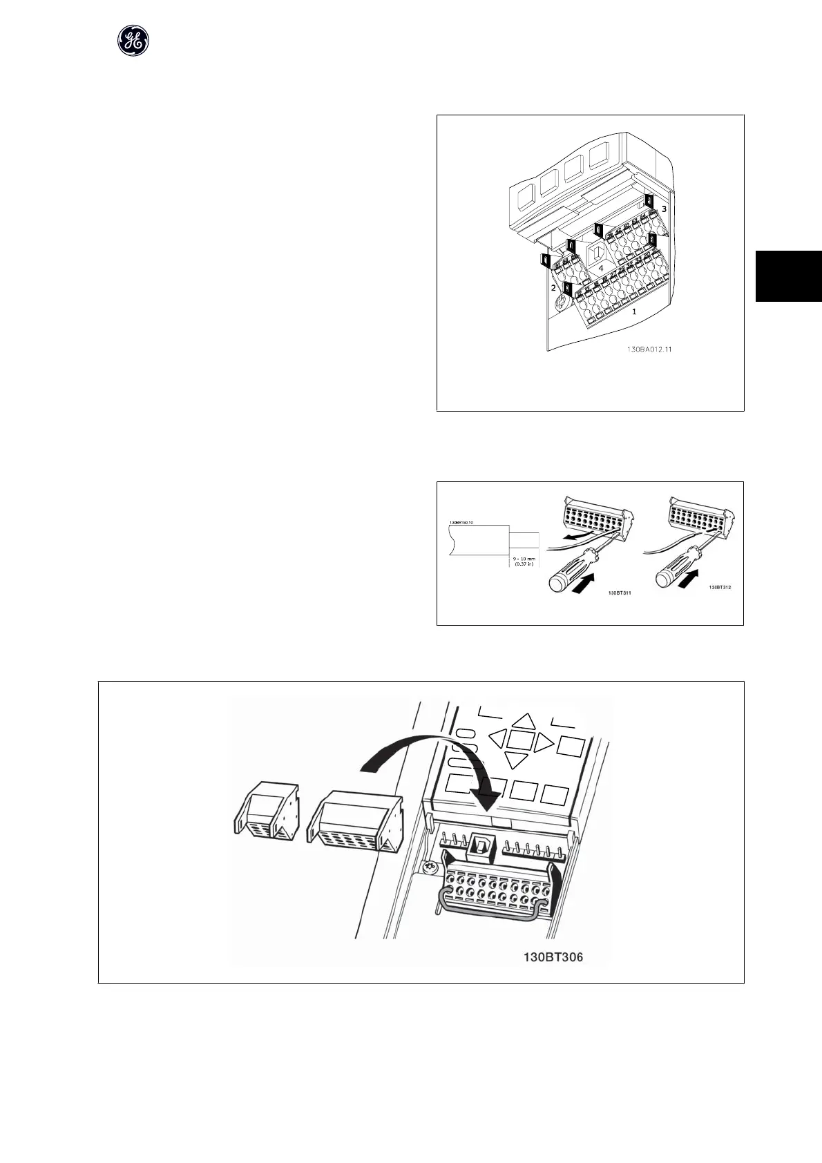
4.2.9 Control Terminals
Drawing reference numbers:
1. 10 pole plug digital I/O.
2. 3 pole plug RS485 Bus.
3. 6 pole analog I/O.
4. USB Connection.
Illustration 4.18: Control terminals (all enclosures)
4.2.10 Control Cable Terminals
To mount the cable to the terminal:
1. Strip isolation of 9-10 mm
2.
Insert a screw driver
1)
in the square hole.
3. Insert the cable in the adjacent circular hole.
4. Remove the screw driver. The cable is now mounted to the terminal.
To remove the cable from the terminal:
1.
Insert a screw driver
1)
in the square hole.
2. Pull out the cable.
1)
Max. 0.4 x 2.5 mm
1.
2.
3.
AF-600 FP Design Guide
79
4

 Loading...


