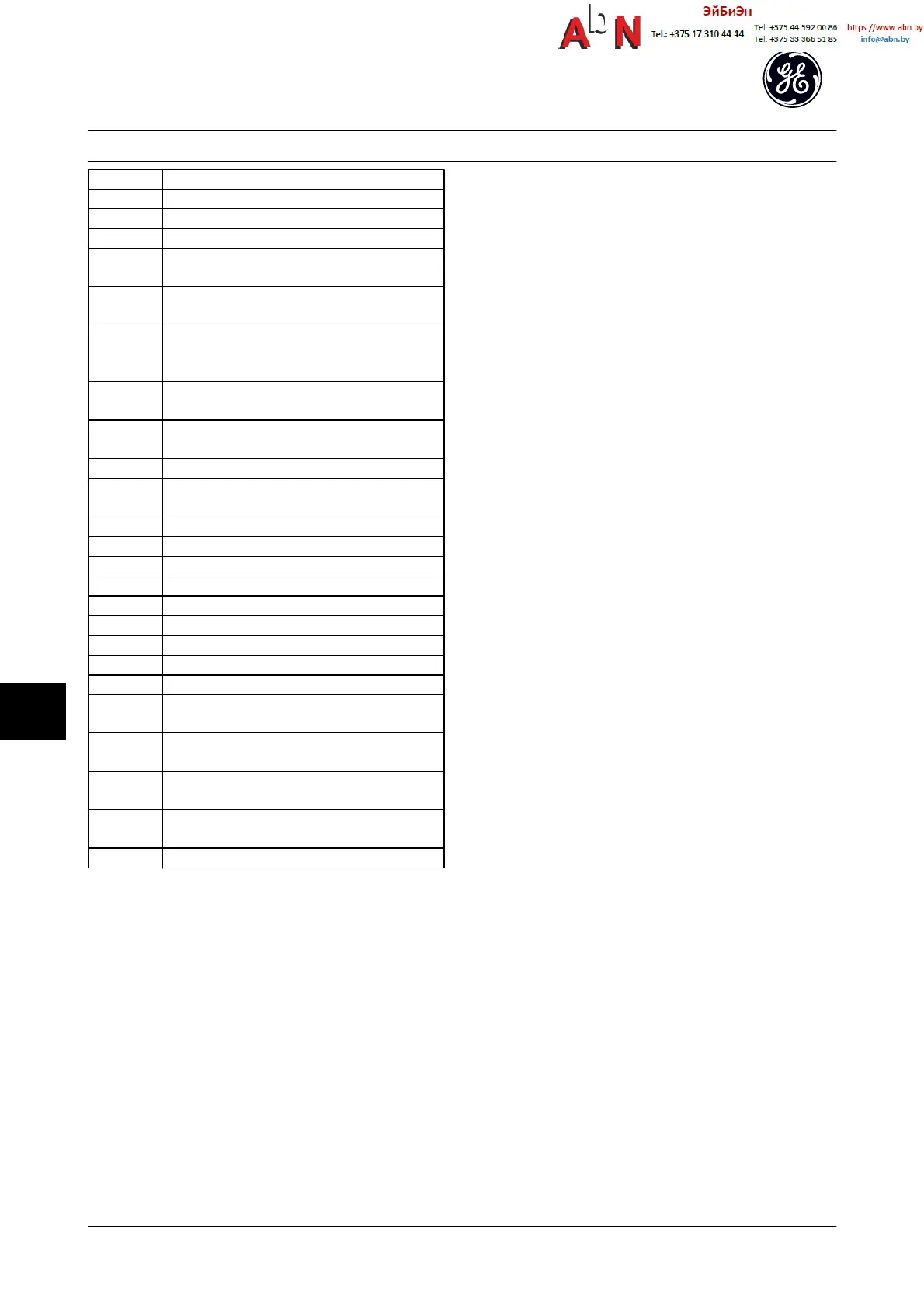
No. Text
2314 Missing power unit data from power unit
2315 Missing SW version from power unit
2316 Missint lo_statepage from power unit
2324 Power card configuration is determined to be
incorrect at power-up
2325 A power card has stopped communicating while
main power is applied
2326 Power card configuration is determined to be
incorrect after the delay for power cards to
register.
2327 Too many power card locations have been
registered as present.
2330 Power size information between the power cards
does not match.
2561 No communication from DSP to ATACD
2562 No communication from ATACD to DSP (state
running)
2816 Stack overflow control board module
2817 Scheduler slow tasks
2818 Fast tasks
2819 Parameter thread
2820 Keypad stack overflow
2821 Serial port overflow
2822 USB port overflow
2836 cfListMempool too small
3072-5122 Parameter value is outside its limits
5123 Option in slot A: Hardware incompatible with
control board hardware
5124 Option in slot B: Hardware incompatible with
control board hardware.
5125 Option in slot C0: Hardware incompatible with
control board hardware.
5126 Option in slot C1: Hardware incompatible with
control board hardware.
5376-6231 Out of memory
Table 10.2
ALARM 39, Heatsink sensor
No feedback from the heatsink temperature sensor.
The signal from the IGBT thermal sensor is not available on
the power card. The problem could be on the power card,
on the gate drive card, or the ribbon cable between the
power card and gate drive card.
WARNING 40, Overload of digital output terminal 27
Check the load connected to terminal 27 or remove short-
circuit connection. Check E-00 Digital I/O Mode and
E-51 Terminal 27 Mode.
WARNING 41, Overload of digital output terminal 29
Check the load connected to terminal 29 or remove short-
circuit connection. Check E-00 Digital I/O Mode and
E-52 Terminal 29 Mode.
WARNING 42, Overload of digital output on X30/6 or
overload of digital output on X30/7
For X30/6, check the load connected to X30/6 or remove
the short-circuit connection. Check E-56 Term X30/6 Digi
Out (OPCGPIO).
For X30/7, check the load connected to X30/7 or remove
the short-circuit connection. Check E-57 Term X30/7 Digi
Out (OPCGPIO).
ALARM 46, Power card supply
The supply on the power card is out of range.
There are three power supplies generated by the switch
mode power supply (SMPS) on the power card: 24 V, 5 V,
±18 V. When powered with three phase AC line voltage, all
three supplies are monitored.
WARNING 47, 24 V supply low
The 24 V DC is measured on the control card. The external
24 V DC backup power supply may be overloaded,
otherwise contact the GE supplier.
WARNING 48, 1.8 V supply low
The 1.8 V DC supply used on the control card is outside of
allowable limits. The power supply is measured on the
control card. Check for a defective control card. If an
option card is present, check for an overvoltage condition.
WARNING 49, Speed limit
When the speed is not within the specified range in F-18
and F-17, the adjustable frequency drive shows a warning.
When the speed is below the specified limit in H-36 Trip
Speed Low [RPM] (except when starting or stopping), the
adjustable frequency drive will trip.
ALARM 50, Auto tune calibration failed
Contact your GE supplier or GE Service Department.
ALARM 51, Auto tune check U
nom
and I
nom
The settings for motor voltage, motor current and motor
power are wrong. Check the settings in parameters P-02,
P-03, P-06, P-07, F-04 and F-05.
ALARM 52, Auto tune low I
nom
The motor current is too low. Check the settings.
ALARM 53, Auto tune motor too big
The motor is too big for the Auto tune to operate.
ALARM 54, Auto tune motor too small
The motor is too small for the Auto tune to operate.
ALARM 55, Auto Tune Parameter out of range
The parameter values of the motor are outside of the
acceptable range. Auto tune will not run.
Warnings and Alarms
AF-650 GP
TM
Design and Installation Guide
10-6 DET-767A
10
0

 Loading...


