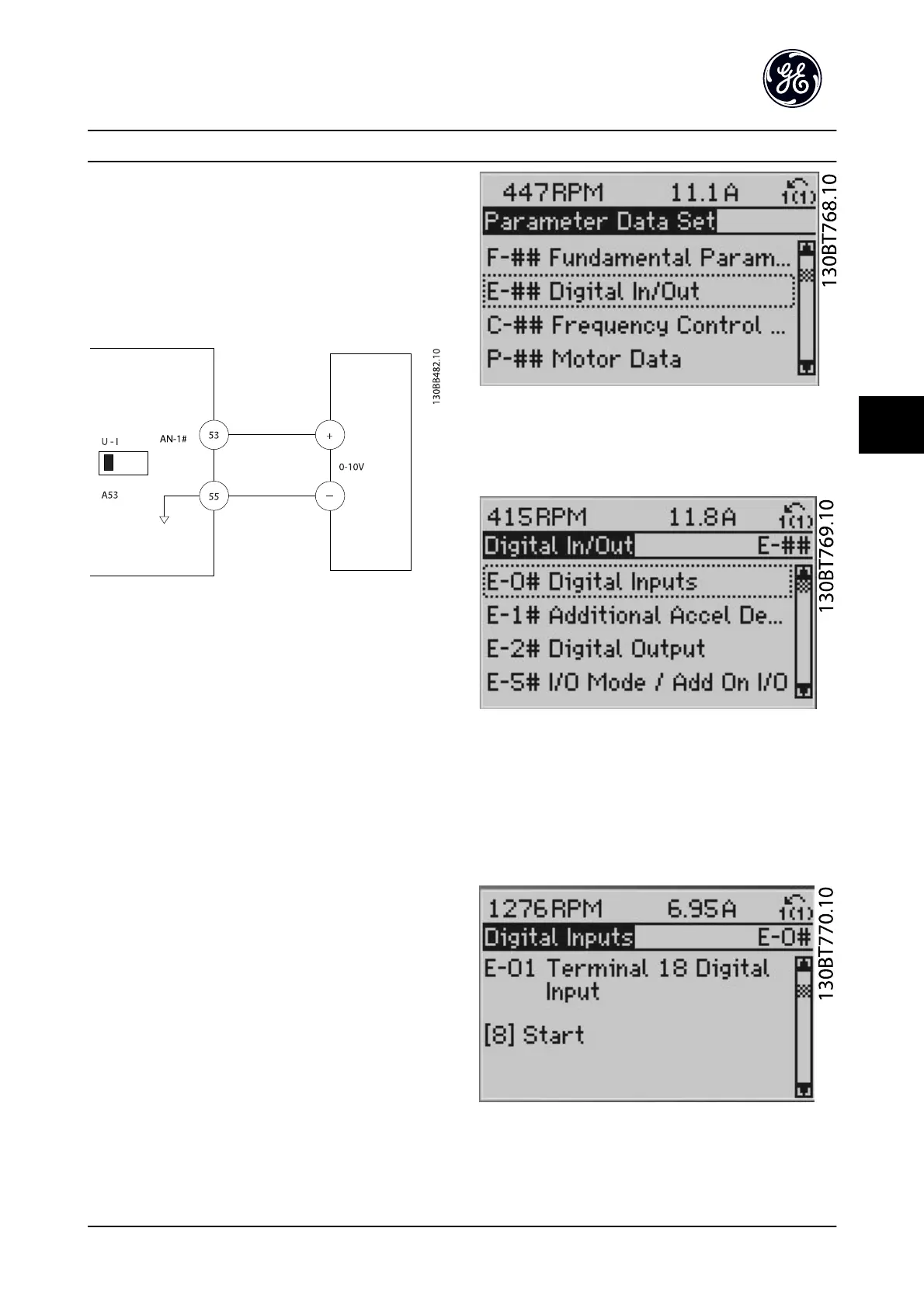
With an external device providing a 0–10 V control signal
connected to adjustable frequency drive terminal 53, the
system is now ready for operation. Note that the scroll bar
on the right in the last figure of the display is at the
bottom, indicating the procedure is complete.
Figure 5.8 shows the wiring connections used to enable
this set-up.
Figure 5.8 Wiring Example for External Device Providing 0–10 V
Control Signal (Adjustable Frequency Drive Left, External Device
Right)
5.3 Control Terminal Programming
Examples
Control terminals can be programmed.
•
Each terminal has specified functions it is capable
of performing.
•
Parameters associated with the terminal enable
the function.
See Table 2.4 for control terminal parameter number and
default setting. (Default setting can change based on the
selection in K-03 Regional Settings.)
The following example shows accessing Terminal 18 to see
the default setting.
1. Press [Main Menu] twice, scroll to and press [OK].
Figure 5.9
2.
Scroll to parameter group E-## Digital In/Out and
press [OK].
Figure 5.10
3. Scroll to parameter group E-0# Digital Inputs and
press [OK]
4. Scroll to E-01 Terminal 18 Digital Input. Press [OK]
to access function choices. The default setting
Start is shown.
Figure 5.11
About Programming
AF-650 GP
TM
Design and Installation Guide
DET-767A 5-3
5

 Loading...


