6.5 PID Control
6.5.1 Speed PID Control
H-40 Configuration Mode
H-41 Motor Control Principle
U/f Advanced Vector Control Flux Sensorless Flux w/ enc. feedb
[0] Speed open-loop Not Active Not Active ACTIVE N.A.
[1] Speed closed-loop N.A. ACTIVE N.A. ACTIVE
[2] Torque N.A. N.A. N.A. Not Active
[3] Process Not Active ACTIVE ACTIVE
Table 6.15 Control Configurations where the Speed Control is active
“N.A.” means that the specific mode is not available at all. “Not
Active” means that the specific mode is available but the Speed
Control is not active in that mode.
NOTE!
The speed control PID will work under the default
parameter setting, but tuning the parameters is highly
recommended in order to optimize motor control
performance. The two flux motor control principles are
particularly dependant on proper tuning to yield their full
potential.
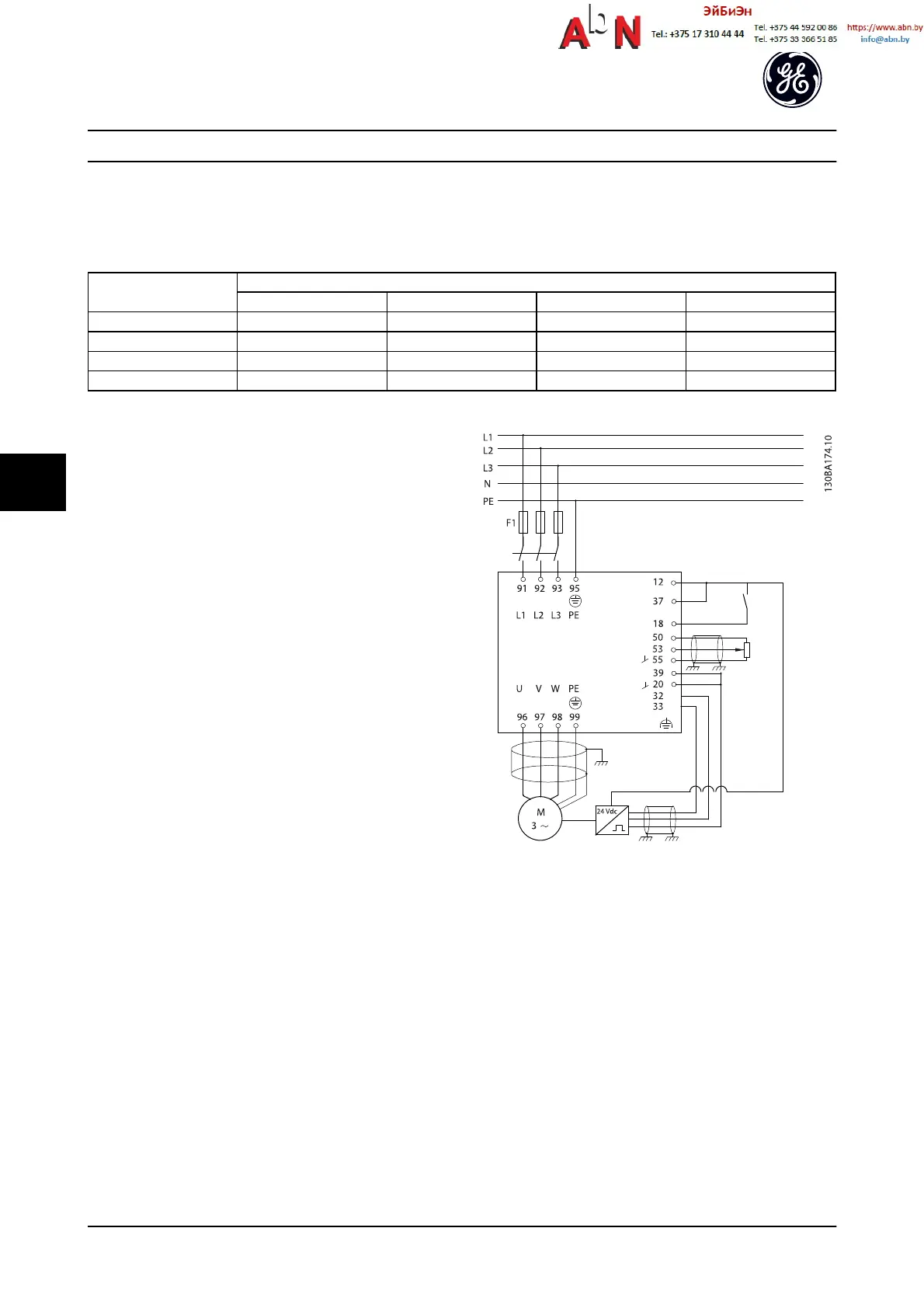
Example of how to Program the Speed Control
In this case, speed PID control is used to maintain a
constant motor speed regardless of the changing load on
the motor. The required motor speed is set via a potenti-
ometer connected to terminal 53. The speed range is 0 to
1,500 RPM corresponding to 0 to 10 V over the potenti-
ometer. Starting and stopping is controlled by a switch
connected to terminal 18. The Speed PID monitors the
actual RPM of the motor by using a 24 V (HTL) incremental
encoder as feedback. The feedback sensor is an encoder
(1024 pulses per revolution) connected to terminals 32 and
33.
Figure 6.17
Application Setup Examples
AF-650 GP
TM
Design and Installation Guide
6-14 DET-767A
6

 Loading...


