Voltage level, logic '1' NPN
2)
< 14 V DC
Maximum voltage on input 28 V DC
Pulse frequency ranges 0–110 kHz
(Duty cycle) Min. pulse width 4.5 ms
Input resistance, R
i
approx. 4 kΩ
Safe stop Terminal 37
2)
(Terminal 37 is fixed PNP logic)
Voltage level 0–24 V DC
Voltage level, logic'0' PNP <4 V DC
Voltage level, logic'1' PNP >20 V DC
Maximum voltage on input 28 V DC
Typical input current at 24 V 50 mA rms
Typical input current at 20 V 60 mA rms
Input capacitance 400 nF
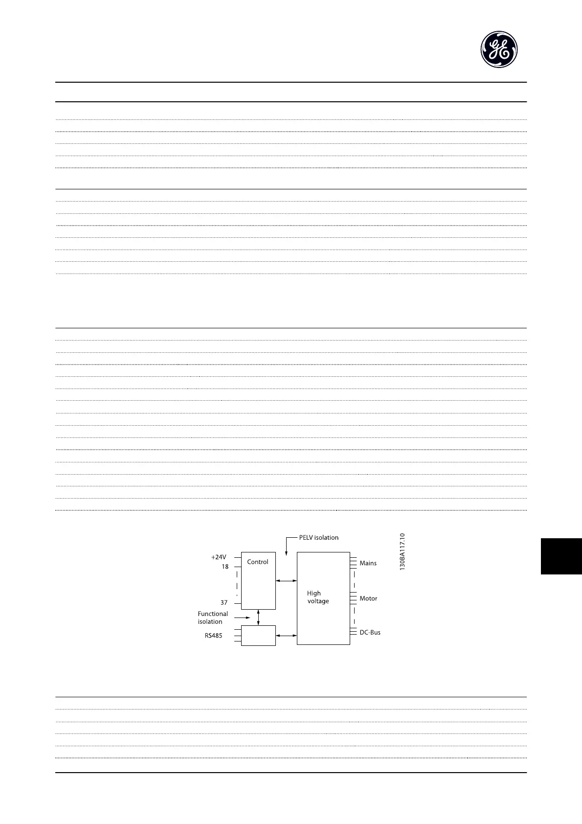
All digital inputs are galvanically isolated from the supply voltage (PELV) and other high-voltage terminals.
1)
Terminals 27 and 29 can also be programmed as output.
2) See 2.5.5.7 Terminal 37 for further information about terminal 37 and Safe Stop.
Analog inputs
Number of analog inputs 2
Terminal number 53, 54
Modes Voltage or current
Mode select Switch S201 and switch S202
Voltage mode Switch S201/switch S202 = OFF (U)
Voltage level -10 to +10V (scaleable)
Input resistance, R
i
approx. 10 kΩ
Max. voltage ± 20 V
Current mode Switch S201/switch S202 = ON (I)
Current level 0/4 to 20 mA (scaleable)
Input resistance, R
i
approx. 200 Ω
Max. current 30 mA
Resolution for analog inputs 10 bit (+ sign)
Accuracy of analog inputs Max. error 0.5% of full scale
Bandwidth 100 Hz
The analog inputs are galvanically isolated from the supply voltage (PELV) and other high-voltage terminals.
Figure 13.22
Pulse/encoder inputs
Programmable pulse/encoder inputs 2/1
Terminal number pulse/encoder 29, 33
1)
/ 32
2)
, 33
2)
Max. frequency at terminal 29, 32, 33 110 kHz (push-pull driven)
Max. frequency at terminal 29, 32, 33 5 kHz (open collector)
Min. frequency at terminal 29, 32, 33 4 Hz
Specifications
AF-650 GP
TM
Design and Installation Guide
DET-767A 13-15
13 1

 Loading...


