Functional description
8-9
Document no. 2044677-001
3.2.3 CPU board
The CPU board contains a processor, memories and all the analog signal processing needed. A
MiniC measuring unit is attached to the board with a flexible PCB. Also supply voltage and an
RS485 serial channel are connected to the CPU board using another flexible PCB.
Analog signals (CO
2
, temperature, absolute and differential pressures and lamp current signals)
are fed to the 16-bit A/D converter. The processor controls the A/D converter and calculates
the CO
2
percentage and respiration rate from this data.
The processor controls sample flow by adjusting the pump voltage based on the differential
pressure signal. The processor also controls the current of the IR source and keeps it constant.
Calibration data is stored on the EEPROM.
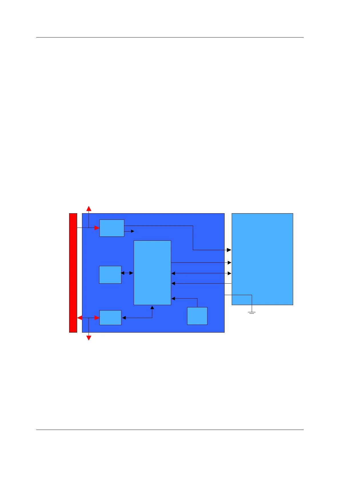
3.2.4 Recorder board
The function of the recorder board is to establish an interface between the recorder unit and
main CPU board in the monitor. The recorder unit related side panel key is connected to the
recorder unit via the recorder board. The recorder unit and the recorder board are connected
together with a special connector. The REC board controls the recorder unit communication
and power.
The REC board is grounded via the recorder unit. If the recorder unit is not installed, the REC
board does not function.
Figure 6 Recorder board block diagram
External Communication
Communication with the main CPU board is established via RS485.
Supply voltage The recorder unit supply voltage, +15V_REC, is provided by the recorder board.
n-frec_block_brd_diag.vsd
Pow
er
Suppl
y
+15
V
CP
U
RS48
5
Driv
er
Dat
a
MODULE BUS
N
V
Memo
ry
Record
er
Uni
t
REC Board
RE
C
Ke
y
Reset
Communicati
on
CT
S
+15V_RE
C
Power
Supply
+15 V
CPU
RS485
Driver
Data
MODULE BUS
NV
Memory
Recorder
Unit
REC Board
REC
Key
Reset
Communication
CTS
+15V_REC

 Loading...


