E-PSM(P)W module introduction
1-41
Document no. 2044677-001
4.5 Connectors and signals
4.5.1 Module bus connector
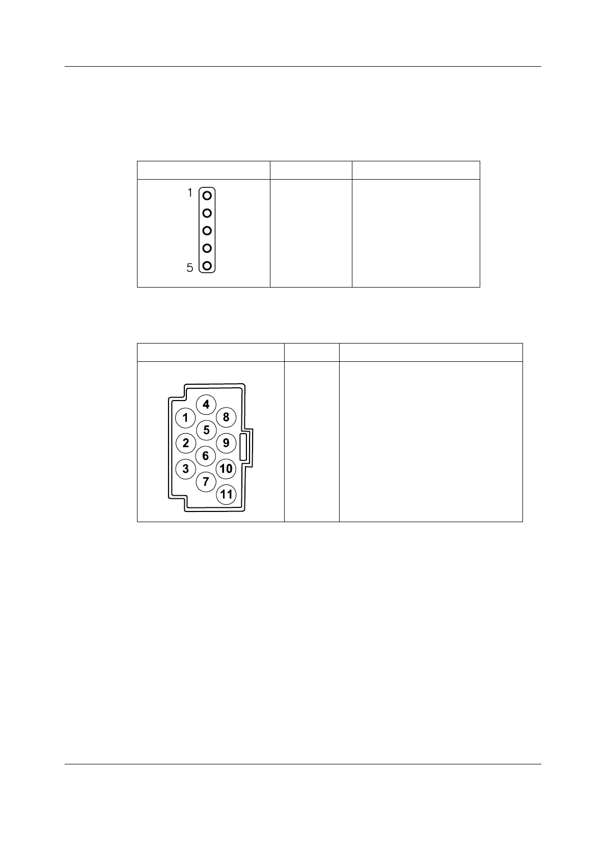
Table 2 Module bus connector description
4.5.2 Front panel connectors
Table 3 ECG connector
5 pin connector Pin No. Signal
1
2
3
4
5
GND
Vmod 13.8 - 16 V
Data +
Data -
Shield
ECG Connector Pin No. Signal Name
1
2
3
4
5
6
7
8
9
10
11
R/RA; Right arm electrode
C2/V2; Chest electrode
C3/V3; Chest electrode
L/LA; Left arm electrode
N/RL; Neutral/Right Leg Drive electrode
C1/V1; Chest electrode
C4/V4; Chest electrode
F/LL; Left Leg electrode
C6/V6; Chest electrode
C5/V5; Chest electrode
Cable Shield

 Loading...


