B30 Patient Monitor
1-42
Document no. 2044677-001
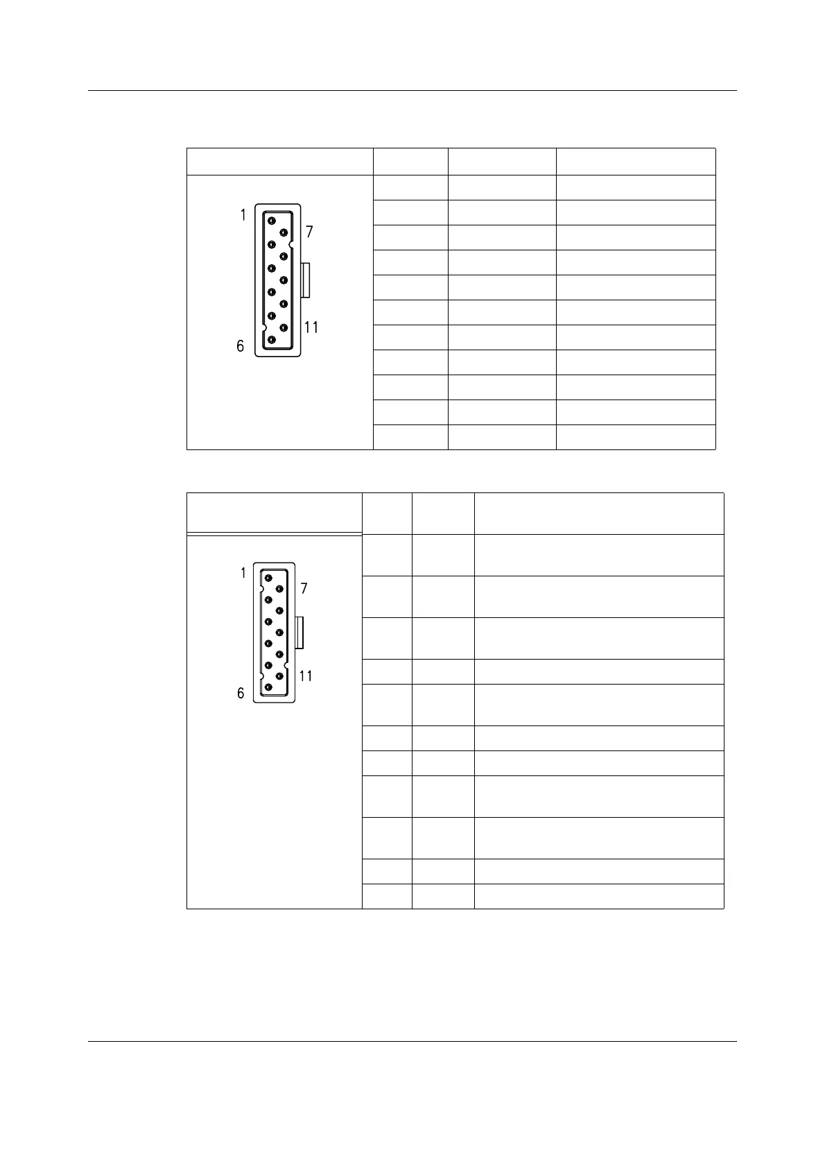
Table 4 SpO
2
connector
Table 5 Invasive blood pressure connectors (P1, P2)
SpO
2
connector Pin No. Signal Description
1 DET_A Photodiode anode
2 DET_C Photodiode cathode
3DATA-
4Wire 1/3LED connection
5 IR_C IR LED cathode
6OUTER SHIELD
7 DET_SHIELD
8 PRB_ID Bin/ID Resistor+
9 Wire 3/5 LED Connection
10 RED_C RED LED cathode
11 DATA+
Invasive blood pressure
connectors (Dual BP)
Pin
No.
Signal Description
1BP_+V
REF
BP transducer excitation voltage, channel
1
2 BP SIG+ BP transducer signal positive (+), channel
1
3BP_+V
REF
BP transducer excitation voltage, channel
2
4 AGND Analog ground
5 BP SIG+ BP transducer signal positive (+), channel
2
6 SHIELD BP cable shield
7 AGND Analog ground
8 BP SIG1 BP transducer signal negative (-), channel
1
9 BP SIG2 BP transducer signal negative (-), channel
2
10 BP1_ID BP1 probe identification
11 NC Not connected

 Loading...


