EasyManuals Logo

GE b30 Technical Reference Manual

GE b30
252 pages
To Next Page IconTo Next Page
To Previous Page IconTo Previous Page
Page #222 background imageLoading...
Page #222 background image
B30 Patient Monitor
8-22
Document no. 2044677-001
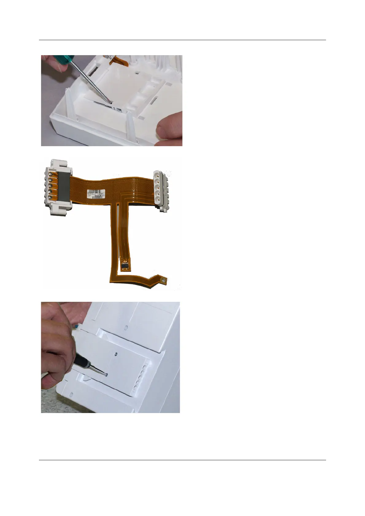
16. Use a flat blade screwdriver to unlock the module
bus connector insulator cover. Put the screwdriver
in the hole and move the blade backwards (away
from the module bus flex cable) until the insulator
cover unlocks.
17. By assisting with a screwdriver pull the module bus
connector through the hole in the module cover.
18. Flip the module cover over and remove the two (T6)
screws holding the lock unit to the frame. While
pulling the tab push the lockers with a screwdriver
to remove the lock unit.

Table of Contents

Other manuals for GE b30

Questions and Answers:

Question and Answer IconNeed help?

Do you have a question about the GE b30 and is the answer not in the manual?

GE b30 Specifications

General IconGeneral
Modelb30
ManufacturerGE
Coil VoltageN/A (Solid State Relay)
Coil PowerN/A (Solid State Relay)
Mechanical LifeN/A (Solid State Relay)
Electrical LifeN/A (Solid State Relay)

Related product manuals