Revision C 170 Series Monitor 5-13
2000947-004
Theory of Operation: Functional Overview
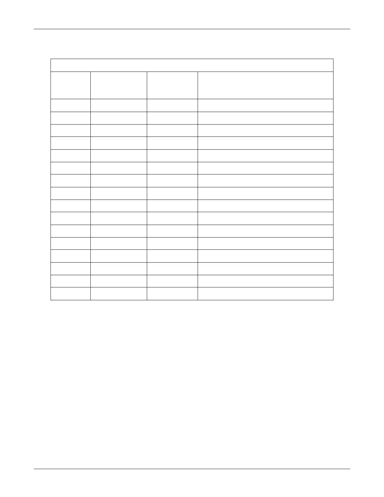
Table 5-14. Display Interface (J18)
Pin Number Signal Name
Signal Type
(Relative To Main
Board)
Signal Description
1 D6 Output Main Board Data Bit 6
2 D5 Output Main Board Data Bit 5
3 D7 Output Main Board Data Bit 7
4 DISPLCS* Output Not Used
5 A0 Output Telemetry ECG (173/174)
6 D4 Output Main Board Data Bit 4
7 D1 Output Main Board Data Bit 1
8 D0 Output Main Board Data Bit 0
9 D2 Output Main Board Data Bit 2
10 D3 Output Main Board Data Bit 3
11 SEGA Output Segment A for Pressure ±1 LED
12 SEGB Output Segment B for Pressure ±1 LED
13 SEGC Output Segment C for Pressure ±1 LED
14 SEGD Output Segment D for Pressure ±1 LED
15 +5V Output +5 Volts for LEDs
16 GND Output Ground for LEDs