Field replaceable units: Remove or replace display assembly
7-22 Dash 3000/4000/5000 2000966-542D
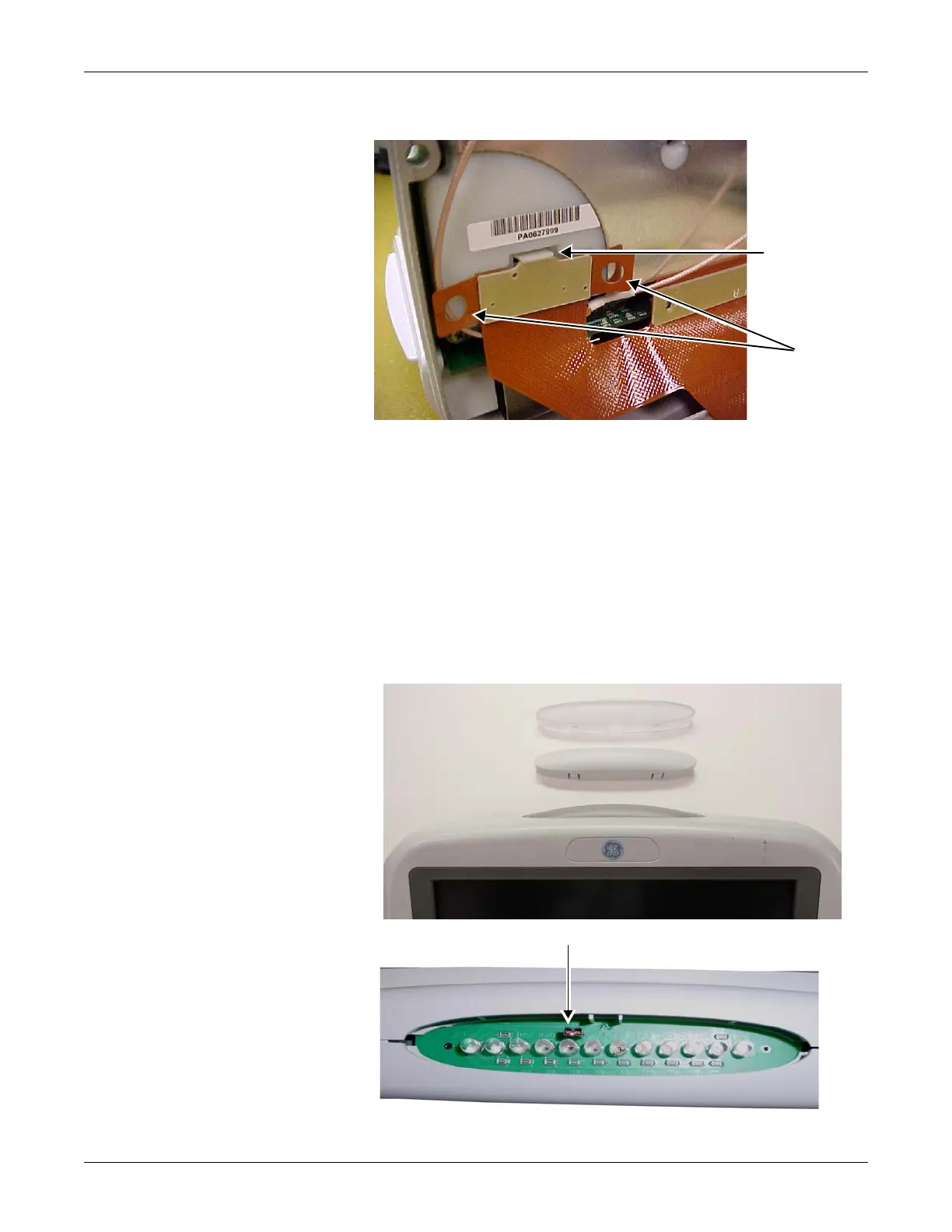
7. Remove the DAS connector by lifting the snap latch and tabs.
8. Place the display assembly face down on a non-static, non-abrasive
surface. Make sure the Trim Knob control hangs off the edge of the
surface to avoid damage.
9. Replace the defective display assembly.
10. To replace the Display Flex assembly, refer to “Replace display flex
assembly” on page 7-24.
11. To replace parts in the main unit, refer to “Replace main unit parts”
on page 7-34.
12. Refer to the figure below to determine if you need to enable or disable
the alarm light on your Dash display assembly.
877A
clear lens
(enable light)
opaque lens
(disable light)
J2 alarm light jumper
878A