Field replaceable units: Remove or replace display assembly
7-18 Dash 3000/4000/5000 2000966-542D
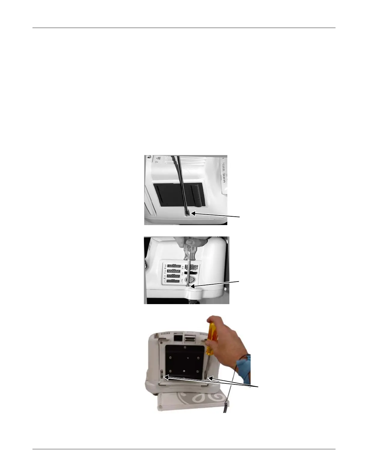
Remove or replace display assembly
1. Remove the handle assembly from the patient monitor. Refer to
“Remove or replace handle assembly” on page 7-10.
NOTE
This step is not necessary for Dash 5000 patient monitors.
2. Place the patient monitor face down on a non-abrasive, static-free
surface. Make sure the Trim Knob control hangs off the edge of the
surface to avoid damage.
3. Use a Phillips head screw driver to remove the four screws (six
screws for Dash 5000 patient monitors) holding the display assembly
to the main unit.
...and the two shorter
screws from the bottom of
the unit.
one screw on the right side of the
unit...
one screw on the left side of the
unit...
579A
578B
580A
Note: Use a screwdriver
with a long blade or
remove the GCX plate first
for easy access to the
bottom screws.