Functional and electrical safety checks: Functional Checkout procedures
8-42 Dash 3000/4000/5000 2000966-542D
DEFIB Sync connector: Marker Out (pulse width)
Signal Pin:—1
Ground Pin:—4
Probe Type:—x10
Time/Division:—5mS
Volts/Division:—1V
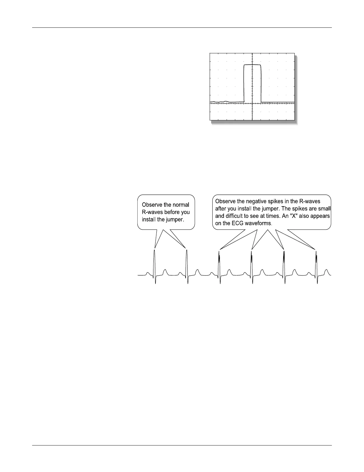
3. Attach a jumper wire between pin-1 (Marker Out) and pin-2 (Marker
In) of the DEFIB SYNC connector located on the back of the patient
monitor. Verify negative spikes in each of the QRS Complex (ECG
waveform) R-Waves on the patient monitor display, similar to those
shown in the illustration below
.
4. Remove the test cables or wires from the DEFIB SYNC connector.
This completes the defibrillator synchronization tests.