g
GE
OPM_SGS_ISG_10K_40K_0US_V010.doc 28/45 Installation Guide SG Series 10, 20, 30 & 40 kVA
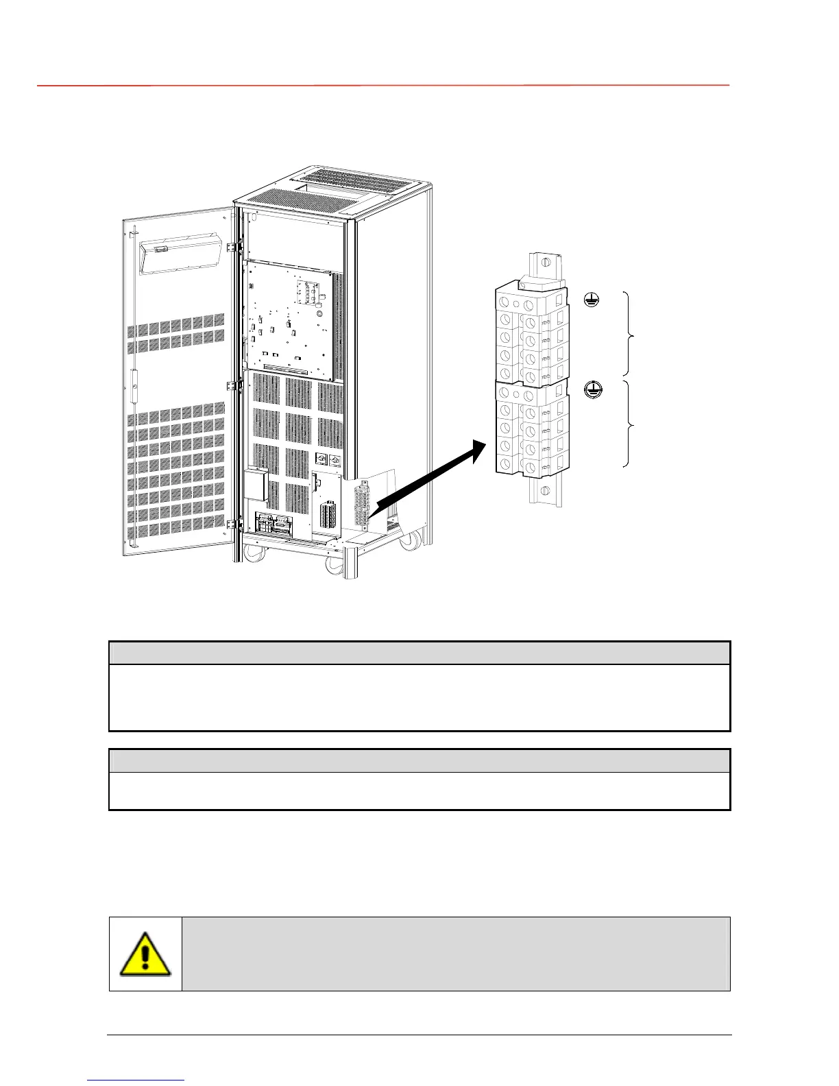
3.8.3 Power connection with common input utility of SG Series 30 and 40 kVA
L1-1
X1
RECTIFIER
1 -
INPUT
L1
LOAD
PE
PE
SGT5000_030-040_UPS connection common_01US
L2
L3
N
L2-1
L3-1
N
OFF
ON
OFF
ON
Fig. 3.8.3-1 Power connections Common Input Utility of SG Series 30 and 40 kVA
SG Series 30 and 40 kVA: Max. rating X1 terminals: 1 AWG (50mm
2
)
Common Input Rectifier / Bypass
L1-1
Rectifier + Bypass Phase A
L2-1
Rectifier + Bypass Phase B
L3-1
Rectifier + Bypass Phase C
N
Neutral (Bypass)
PE
Ground
Output Load
L1
Load Phase A
L2
Load Phase B
L3
Load Phase C
N
Neutral
PE
Ground
The interconnection links BR1, BR2 and BR3 must remain connected.
Cable terminations are to the Rectifier Input Terminals and Output Terminals as shown above.
Connect wire to the Terminals using appropriate tools and appropriate torque.
Torque specification for Input / Output and DC power connections on Terminals: Section 3.8.1.
This UPS is only designed to operate in a wye-configured electrical system
with a solidly grounded neutral.
If the UPS is equipped with an input transformer, the secondary of the
transformer must be wye-configured with neutral solidly grounded.
 Loading...


