g
GE
OPM_SGS_ISG_10K_40K_0US_V010.doc 31/45 Installation Guide SG Series 10, 20, 30 & 40 kVA
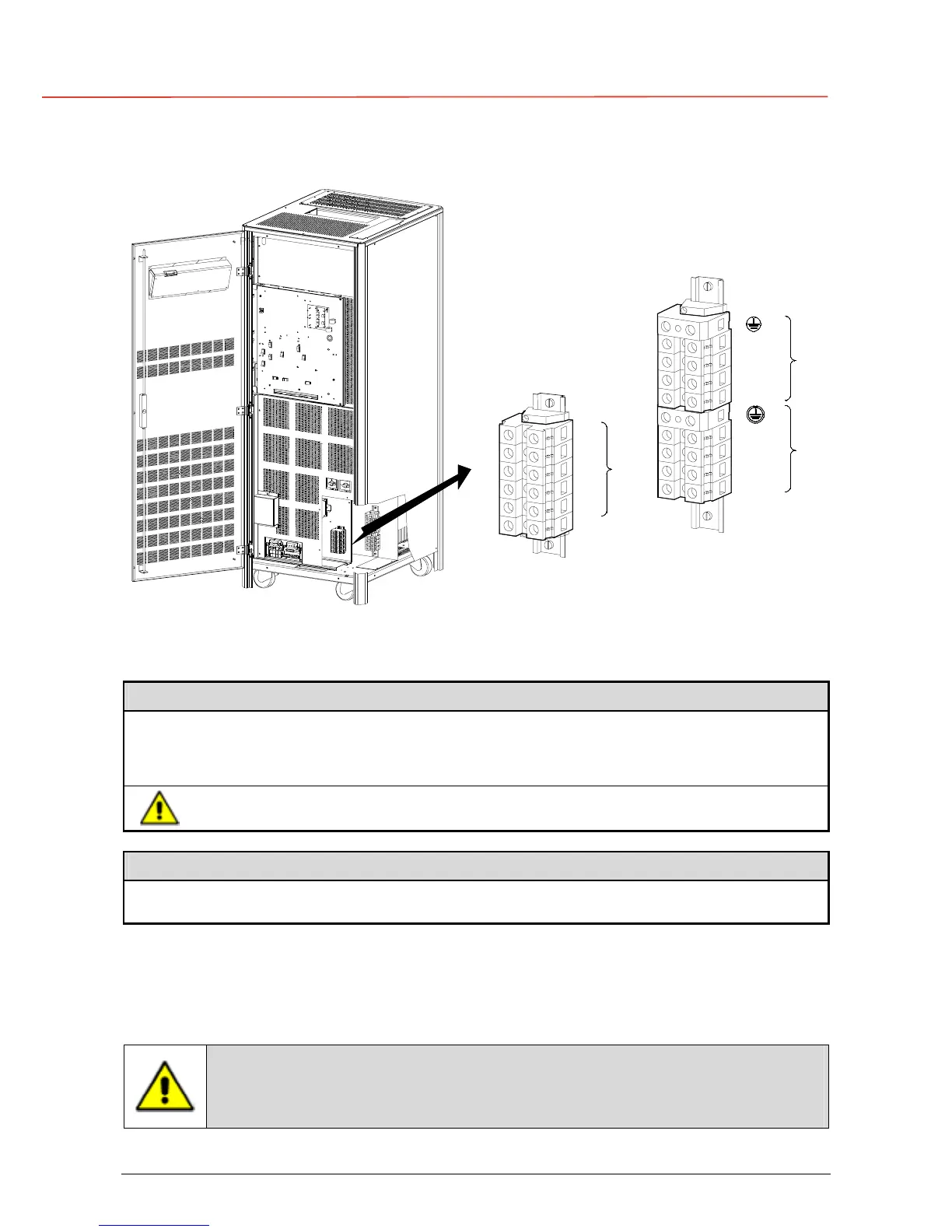
3.8.5 Power connection separate input utility of SG Series 30 and 40 kVA
L1-1
X1
L1
PE
PE
SGT5000_030-040_UPS connection separate_01US
L2
L3
N
L2-1
L3-1
N
OFF
ON
OFF
ON
2- INPUT BYPASS
L1-2
L2-2
L3-2
X2
L3
L2
L1
RECTIFIER
INPUT
1 -
LOAD
Fig. 3.8.5-1 Power connections Separate Input Utility of SG Series 30 and 40 kVA
SG Series 30 and 40 kVA: Max. rating X1 and X2 terminals: 1 AWG (50mm
2
)
Separate Input Rectifier / Bypass
L1-1
Rectifier Phase A
L1-2
Bypass Phase A
L2-1
Rectifier Phase B
L2-2
Bypass Phase B
L3-1
Rectifier Phase C
L3-2
Bypass Phase C
N
Neutral (Bypass)
PE
Ground
The interconnection links BR1, BR2 and BR3 must be removed (see Fig. 3.8.5-2).
Output Load
L1
Load Phase A
L2
Load Phase B
L3
Load Phase C
N
Neutral
PE
Ground
The interconnection links BR1, BR2 and BR3 must be removed.
Cable terminations are to the Rectifier / Bypass Input Terminals and Load Output Terminals as
shown above.
Connect wire to the Terminals using appropriate tools and appropriate torque.
Torque specification for Input / Output and DC power connections on Terminals: Section 3.8.1.
This UPS is only designed to operate in a wye-configured electrical system
with a solidly grounded neutral.
If the UPS is equipped with an input transformer, the secondary of the
transformer must be wye-configured with neutral solidly grounded.
 Loading...


