g
GE
OPM_SGS_ISG_10K_40K_0US_V010.doc 40/45 Installation Guide SG Series 10, 20, 30 & 40 kVA
SGT5000_030-040_RPA control bus cable_02US
N
e
x
t
p
a
r
a
l
l
e
l
u
n
i
t
3
,
4
,
5
,
6
,
7
,
8
JB2
JA2
U
P
S
1
JA1
JB1
JA1
JB1
JB
JA
JB1
JB2
JB
JA
JA2
JA1
JA2
U
P
S
2
Q2
Q1
OFF
ON
OFF
ON
JB2
A
A
ON
OFF
Q1
Q2
ON
OFF
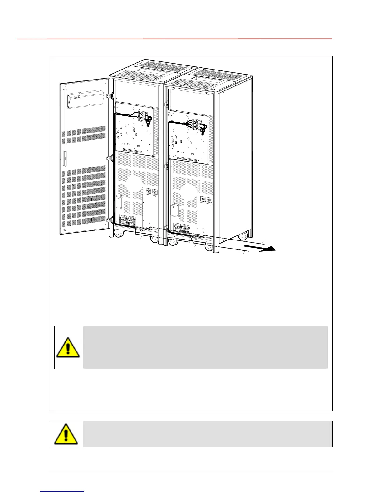
Fig. 3.11-3 Control Bus cable routing and connection
Control bus cables routing
Place and fix the cables JA-1/2/3/4/5/6/7 and JB-1/2/3/4/5/6/7 with the appropriate clamps
inside the UPS cabinets in the position shown in the drawing Fig 3.11-1/2/3.
Pay attention to the fact, that routing of cables shall allow the removal of the protection covers
“A”.
Pay attention when cabling and routing the bus cables JA and JB inside the
UPS cabinet.
In case one unit should be removed from the parallel system, the bus cables
JA and JB must be removed from the cabinet without disconnecting them
from the metal plate where the sockets JA and JB are located.
For reliability reasons the cables JA-1/2/3/4/5/6/7 and JB-1/2/3/4/5/6/7 connecting the units
should be run in separated protected conduits (as indicated in fig. 3.11-3) separated from the
power cables.
It is important that the cable JA must be the same length as cable JB.
The connection of the control bus cable in a UPS system already powered
requires a special reset operation, which can be made by only a trained
operator.
 Loading...


