2018112-003 Rev J eBike, eBike L, eBike EL - 75 -
Appendix A: Interfaces
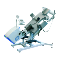
The modular ergometer system
eBike
has several interfaces. Digital as well as analog data can be
exchanged with the ergometer. These interfaces thus allow the ergometer to be fully controlled from a
PC or EKG unit and they also permit a mere transfer of data from the ergometer to the EKG unit and
PC.
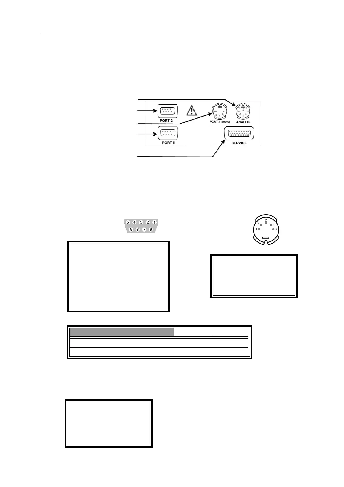
Analog interface
PORT 2 (9-pin SUB-D)
PORT 3 (5-pin DIN socket)
PORT 1 (9-pin SUB-D)
multi-purpose port
A.1 Digital Interfaces PORT 1 and PORT 3
A.1 a Setup for: Digital ECG Unit
PORT 1: PORT 3:
Digital interface RS 232 + remote start Digital interface RS232
• Pin configuration
(view of connector):
Pin 1 -
Pin 2 Receive (Input)
Pin 3 Transmit (Output) Pin 1 TxD
Pin 4 - Pin 2 GND
Pin 5 GND PIN 3 -
Pin 6 - Pin 4 -
Pin 7 - Pin 5 RxD
Pin 8 remote start EKG unit
Pin 9 -
• Voltages:
logic low logic high
Transmit Output (Pin 3 or Pin 1) > +7 V > -7 V
Receive Input (Pin 2 or Pin 5) > +3 V > - 3 V
• Baudrate (adjustable via software menu):
default setting: 4800 Baud
available settings: 1200, 2400, 4800, 9600, 19200, 38400, 57600, 115200 Baud
• Protocol:
Format: ASCII
Start bit: 1
Data bit: 8
Stop bit: 1
Parity: None
Handshake: None
Appendix A: Interfaces