- 17 of 40 -
4400-0024-EN Rev A
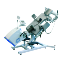
1. Turn Controller over.
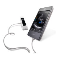
Diagram 1 Diagram 2
Controller Model 121
L
O
C
K
U
N
L
O
C
K
Controller Model 121
L
O
C
K
U
N
L
O
C
K
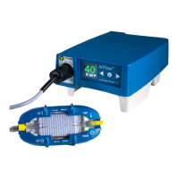
2. To remove the bottom, unscrew pole clamp screw; unscrew six (6) screws shown below. Next, lift the cover.
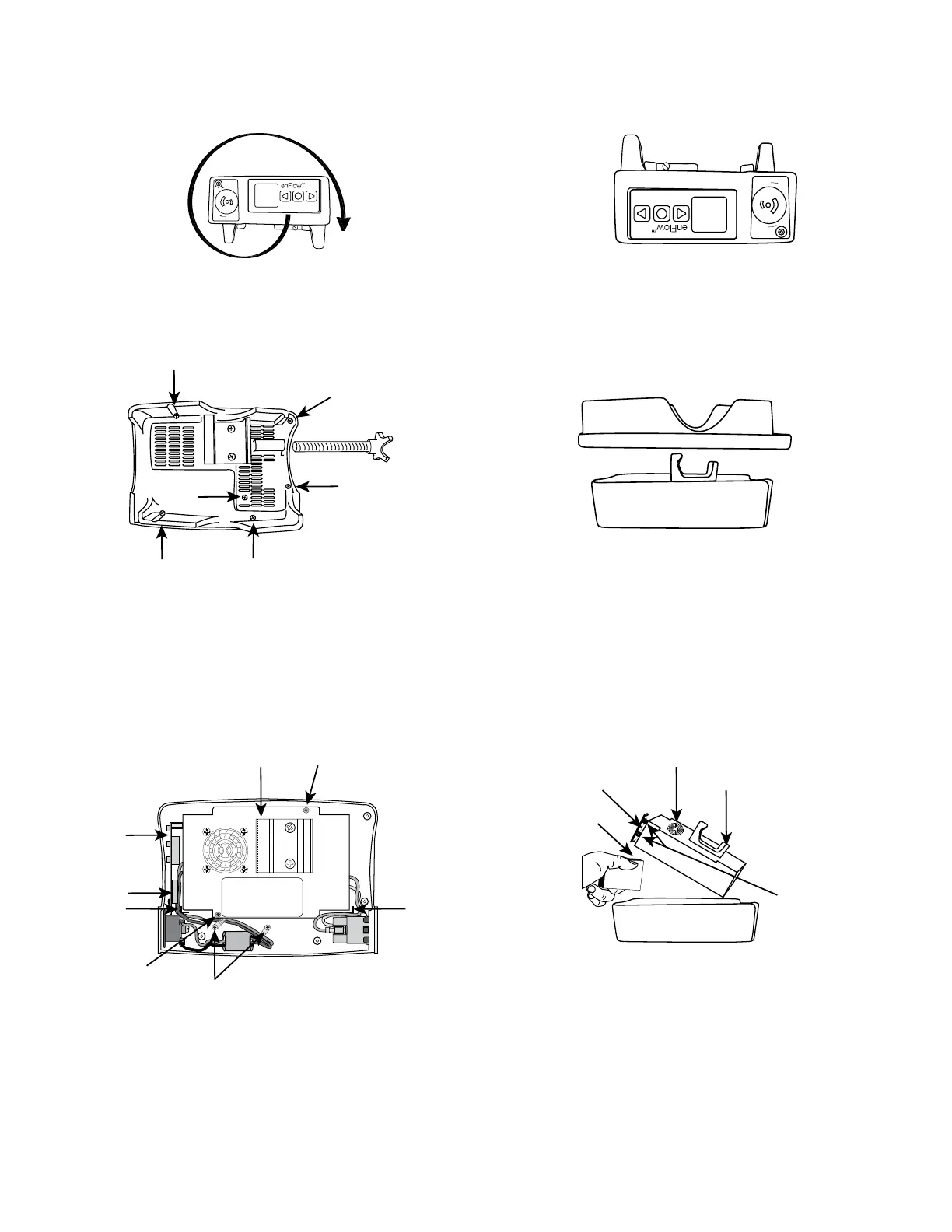
Diagram 3 Diagram 4
Screw_5
Screw_6
Screw_3
Screw_4
Screw_2
Pole Clamp Screw
3. Remove power supply assembly
a. On the power supply assembly, unscrew two (2) screws shown below (see Diagram 5). Also remove the screws holding the zip ties to the post for the
ferrite bead securement.
b. Gently lift assembly by holding pole clamp, and prop up with a small block or box (see Diagram 6).
Diagram 5 Diagram 6
Zip ties
Screw_2
Display
Board
Battery
Post_1
Post_2
Display Board
Block
White Posts
Pole Clamp
 Loading...