- 20 of 40 -
4400-0024-EN Rev A
Conrm the enFlow and the ECG monitor are plugged into dierent outlets
There are two reasons for this action. It is possible that the two systems are in an electrical phase related conict, which is being expressed on the monitor.
Secondly, it is possible that the outlets are not properly grounded or grounded in dierent locations. While rare, it can be the case and outwardly there would
be no way to tell.
Conrm the Warmer cord is not entwined or near the ECG lead cable
Separating the two cords will allow each cable’s shielding to work to its full potential.
Conrm the monitoring cables and lead wires are in proper working order
The insulating layer on lead wires and cables degrades over time and with use. Conrm the insulation is intact and operates at its stated specications.
Review the monitor’s notch lter
Check to ensure that the monitoring system’s frequency lter is set appropriately.
Determine the monitor’s sensitivity setting
Many physiological monitors have the ability to interpret electrical signals in two distinct modes: a highly sensitive “Diagnostic” mode or a more ltered
“Monitoring” mode. Determine the current mode of operation. If the current mode is set on “Diagnostic” consider adjusting it to “Monitoring.”
Check the ECG pads impedance
Contact your current supplier of monitoring pads or your local Vital Signs representative to determine if a lower impedance version is available. High
impedance monitoring pads are less sensitive to the very low signal strength from the heart beat and appear to be more prone to pronounced interference.
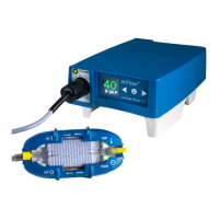
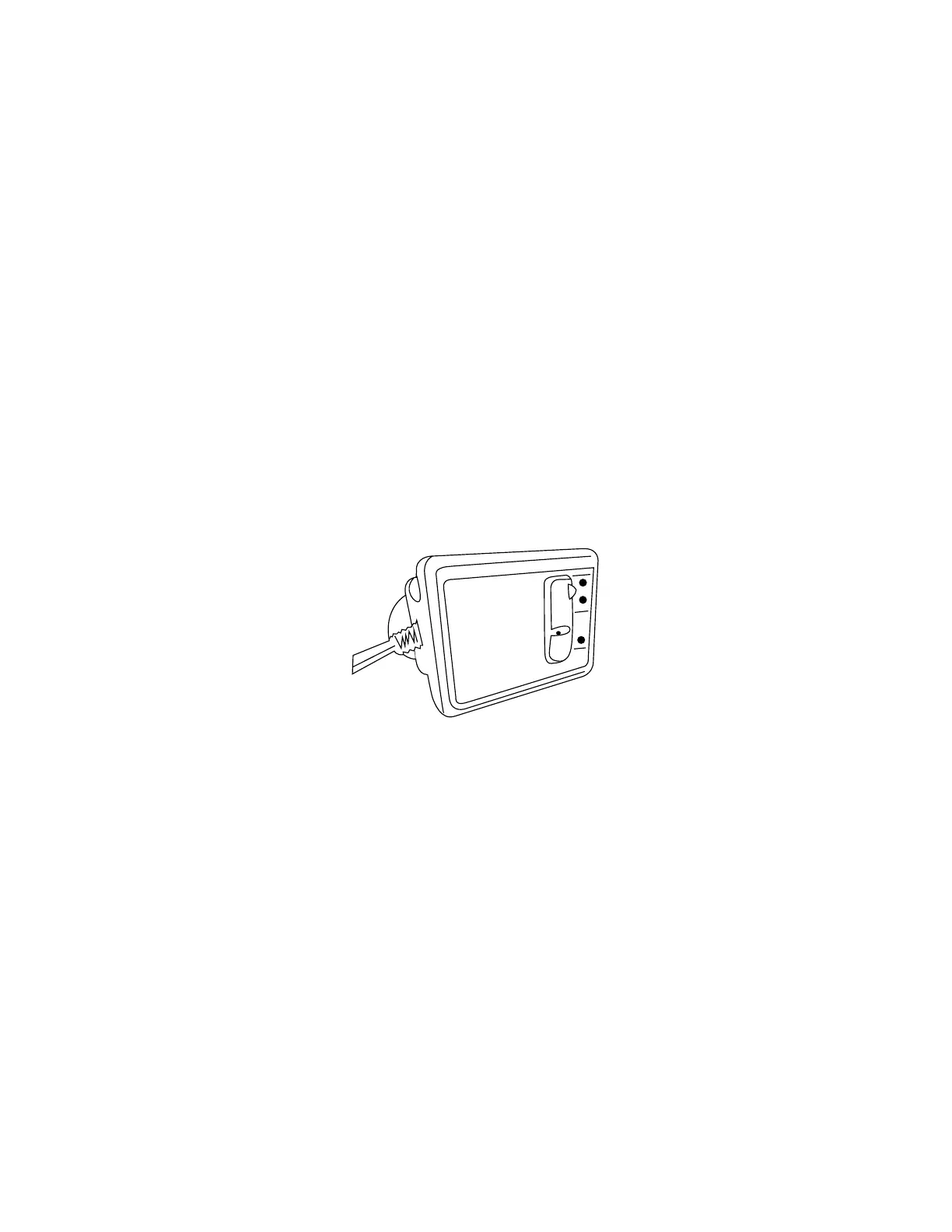
enCheck (Model 400) user guide
Intended use
Use this product only for the purpose for which it was designed; refer to product description below.
Purpose
The enCheck tester was developed to quickly and reliably trigger the over-temperature alarm condition on the enFlow Warmer. Within seconds, the enCheck
unit will heat the Warmer to an over- temperature scenario causing the alarm to sound. Additionally, the enCheck is designed to verify the Warmer operation
at enFlow’s installation site.
Procedure
When the enCheck is connected and running in the normal mode, the heat is generated from the Warmer unit using the same technology as when a
cartridge is installed. This mode allows for conrmation of the temperature output of the Warmer. (See Appendix E, section on “Simulated Use Performance
Testing.”)
enCheck system description
The enCheck is designed to verify the Warmer operation at enFlow’s installation site. In the Normal Mode, it allows for conrmation of the temperature
output of the Warmer. In the Overheat Mode, it heats the Warmer to an over-temperature scenario causing the alarm to sound.
 Loading...