- 28 of 40 -
4400-0024-EN Rev A
Appendix E: Preventive maintenance procedure
Employ local regulations to determine the frequency of required testing (i.e. Earthing Impedance, Leakage Current) for the enFlow Warmer (Model 100) and
Controller (Model 121).
Frequency
Functional and Operational Testing Protocols As required by accrediting body or once a year
Inspections X
Temperature Readout Display and Status Indicator Lights X
Electrical Safety X
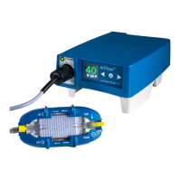
Simulated Use Performance Testing: enCheck Model 400 or Alternative Method X
Alarm Test: enCheck Model 400 or Alternative Method X
Inspections
1. Ensure all cords and connectors are in good condition and void of any cuts, cracks, or frays. Discoloration from cleaning solutions and disinfectants is
normal and to be expected.
2. Ensure the unit is clean and void of any cracks or other signs of damage. If signs of damage are visible, remove it from service and contact Vital Signs as
soon as possible.
Temperature readout display and status indicator lights
1. Plug the Controller into a functioning power supply. Set the MAINS power to ON. Conrm the Controller power indicator is illuminated and displaying a
green color. Conrm the display panel (Controller only) shows in yellow the conditional message “not heating.”
2. Connect the Warmer without a Disposable Cartridge inside to the Controller. Conrm the beep signaling connection. Conrm the display continues to
show the conditional message “not heating.” Conrm the Warmer power LED is ashing green.
Electrical safety
1. Ground wire resistance
Equipment
enFlow Controller
Safety analyzer with test lead
Purpose
The purpose of this test is to check the resistance in ohms of the ground pin to the chassis. For purposes of this check, the pole screw will be considered to be
the ground pin, and the chassis is the Controller.
Procedure
A. USA (Tests the equipment inclusive of its power cord.)
1. Remove the Controller from the IV pole.
2. Reinsert the pole clamp screw; screw in tight against the case. (Do not over-tighten.)
3. Attach the banana end of the ground lead on the safety analyzer to the pole clamp screw.
4. Plug the power cord of the Controller into the safety analyzer.
5. Set the function knob on the safety analyzer to ground wire resistance.
6. Set the ground switch to normal.
7. Set the polarity switch to the o position.
8. Power the safety analyzer by plugging in and setting the MAINS power to ON.
9. Record the resistance reading. An acceptable reading is a maximum of 500.0 mΩ.
B. TUV (Tests the equipment exclusive of its power cord.)
1. Follow steps 1-3 in Procedure A.
2. Plug the cord of the safety analyzer into the Controller.
3. Follow steps 5-8 in Procedure A.
4. Record the resistance reading. An acceptable reading is a maximum of 100.0 mΩ at a current of 25 A.
 Loading...