- 34 of 40 -
4400-0024-EN Rev A
enFlow
Warm er
T hermometer
Temperature
probe
inserted into
extension set.
Waste water
container
IV Line set
Extension set
enFlow
Controller
Power
source
Pump
100
mL/min
Temperature
probe
inserted into
extension set.
Extension set
.5 L
Water source
20 °C
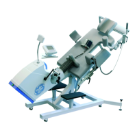
Procedure
Measure input and output temperature of uid: standard ow
1. Set up the enFlow system for normal operation.
2. Attach an IV line set to a 0.5 liter source of uid at a temperature of ≈ 20 °C ± 2 °C. Then run the IV line through a pump capable of maintaining up to
200 mL/min or determine ow rate using the graduated cylinder and timer.
3. Next, attach the IV line to the enFlow system.
4. The temperatures for this test should be measured within 22.9 cm (9 in) of both the input and output connections of the Disposable Cartridge. This step is
done by inserting T connectors in the direct uid paths, which will accommodate a temperature probe. Connect the temperature probes to a thermometer
capable of measuring between 10 °C and 60 °C with ± 0.1 °C accuracy.
5. Prime the IV line setup according to standard IV protocols.
6. Conrm the output end of the extension set empties into the waste water container.
7. Power on the enFlow system, and establish a uid ow of 100 ± 20 mL/min. Then allow at least 20 seconds for the power-on self-test to complete, the
temperature display to read a stable temperature, and the temperature probes to stabilize.
8. Record the input uid temperature. The acceptable temperature range is 20 °C ± 2.0 °C.
9. Record the output uid temperature. The acceptable temperature range is 40 °C ± 2.0 °C.
10. It is recommended to repeat steps 1-9 for the ow rate of 60 mL a minute.
Measure input and output temperatures of uid: high ows
11. Repeat steps 1-7 for the high ow rates of 125± 20 mL/min, 175 ± 20 mL/min, and 200 mL/min. However, in place of steps 8 and 9, measure the rise in
temperature of the output uid over the input uid value. The rise should be >16.5 °C.
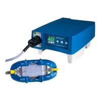
Alarm test
A. enCheck Model 400
1. enCheck Model 400 (includes “K” type probe)
2. enFlow Controller/AC Power Pack (Model 121)
3. enFlow Warmer (Model 100)
4. Calibrated Thermometer with ± 0.5 °C accuracy (Fluke 54 or equivalent)
Test procedure
Alarm function test:
1. Plug the enFlow Controller into an AC outlet.
2. Conrm that the switch on the enCheck is set to the normal mode.
3. Connect the enCheck to the enFlow Controller, by inserting the male plug end of the enCheck Hubbell connector into the female receptacle on the front
face of the enFlow Controller. Push in and twist the enCheck Hubbell connector so that the plug cover is locked snugly against the receptacle.
4. Connect the enFlow Warmer to the enCheck by inserting the male plug end of the Warmer into the female receptacle of the enCheck. Push the plugs
together and twist to lock them snugly against each other.
5. Insert the enCheck temperature probe connector into the Calibrated Thermometer and set the Thermometer to “K” type setting.
 Loading...