Appendix A: Panel specifications
202 EST iO64 and iO500 Technical Reference Manual
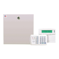
Control panel specifications
64 point panel 250/500 point panel
Device loops 1 loop Class B or Class A (Styles 4, 6, 7)
supporting up to 64 device addresses (any
combination of detectors and modules)
1 loop, expandable to 2, Class A or B (Styles
4, 6, 7), each loop supporting up to 250
device addresses (125 detectors and 125
modules max.). Note: Addresses 1 to 125
are for detectors and addresses 126 to 250
are for modules.
Notification appliance circuits 2 Class B (Style Y), Class A (Style Z) optional
3.75 A FWR total at 120/230 VAC 60 Hz
3.0 A FWR total at 230 VAC 50 Hz
2.5 A FWR each max. per circuit
4 Class B (Style Y) or 2 Class A (Style Z)
6.0 A FWR total at 120/230 VAC 60 Hz
5.0 A FWR total at 230 VAC 50 Hz
2.5 A FWR each max. per circuit
Primary power 120 VAC, 60 Hz, 1.3 A max.
230 VAC, 50-60 Hz, 0.6 A max.
120 VAC, 60 Hz, 1.8 A max.
230 VAC, 50-60 Hz, 0.975 A max.
Base panel current standby 155 mA 172 mA
Base panel current alarm 204 mA 267 mA
Input zones 16 max. 32 max.
Remote annunciator 8 drops max., RS-485 Class B, Class A optional
Data line length: 4,000 ft. (1,219 m)
8 drops max., RS-485 Class A or B
Data line length: 4,000 ft. (1,219 m)
Operating voltage 24 VDC
Auxiliary power output circuit Aux power 1: 500 mA, 24 VDC
Aux power 2: 500 mA, 24 VDC (1 A possible if you reduce total available NAC power by 500 mA)
Output: 28.3 to 21.9 VDC, special application
Note: For a complete list of devices that can be connected to this circuit, refer to the iO64 and
iO500 Series Compatibility List (P/N 3101064).
Loop circuit Maximum loop resistance: 66
Maximum loop capacitance: 0.2 µF
Communication line voltage: Maximum 20.6 V peak-to-peak
Operating current (fully loaded loop)
Stand by: 60 mA
Alarm: 125 mA (this does not include two-wire smoke modules)
Circuit current: 0.5 A max.
Style 4, 6, and 7 wiring
Max. resistance between isolators: Limited only by overall wire run lengths
64 isolators maximum (total both isolator bases and modules)
Batteries Type: Sealed lead acid
Voltage: 24 VDC
Charging current: 2.47 A max.
Amp hour capacity: 26 Ah
Standby operation: 24 hour or 60 hour
Placement: Up to two 10 Ah batteries will fit in the 64 pt control panel cabinet and two 18 Ah
batteries will fit in the 250/500 point control panel cabinet. If larger batteries are required, you
must use a GE Security battery cabinet.

 Loading...

