Appendix D: Applications
EST iO64 and iO500 Technical Reference Manual 259
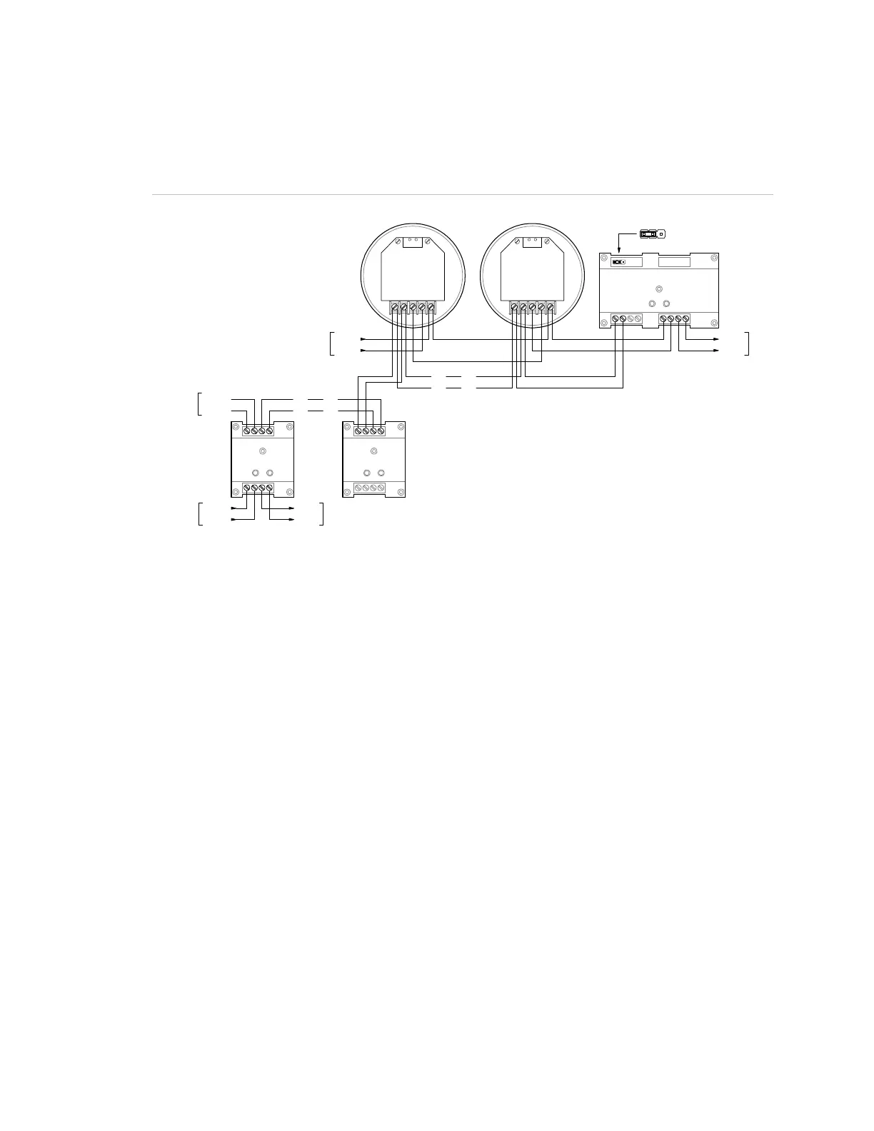
Typically, the 24 VDC riser that supplies power to the audible
detector bases is supervised using an RM1 Riser Monitor module.
You can also use a CT1 module and a PAM-1 control relay.
Wiring
12
3
4
56
7
8
RM1
SIG+
SIG-
DATA- OUT
DATA- IN
DATA+ IN/OUT
SIG+
SIG-
DATA- OUT
DATA- IN
DATA+ IN/OUT
DATA+
DATA-
SLC
DATA+
DATA-
SLC
FIRST
DETECTOR
LAST
DETECTOR
7
8
1234
65
G1M-RM
78
12
3
4
65
CRR
SLC
DATA+
DATA-
DATA+
DATA-
24 VDC+
24 VDC-
AUX RISER
NORMALACTIVE
-+
+-
SLC
NORMALACTIVE
-+
+-
N.C.
N.C.
JP1: 24 VDC Monitor
Programming
1. Set the panel’s Event Notification option for Device.
2. Configure the smoke detectors as follows:
Device Type: Smoke or Smoke Heat depending on the detectors
used
Message Line 1: SMOKE_<N>, where <N> can be the device
address or other number
Message Line 2: As required
Coder: 0-0-0-0
Sensitivity: As required
Alt Sensitivity: As required
Pre Alarm: Any value other than None
Alt Pre Alarm: Any value other than None
Verification: N/A
Alt Verification: N/A
Base: Relay/Sounder
Follow Alarm: No
 Loading...