Chapter 2: Installation and wiring
EST iO64 and iO500 Technical Reference Manual 79
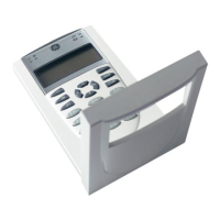
Alarm and trouble transmitted on a single circuit
Note: JP1 on the RPM must be OUT.
From ALRM on RPM (brown wire)
From TRBL on RPM (yellow wire
From COM on RPM (black wire)
From +24 on RPM (red wire)
ontrol panel
TB3
TRBL
C
NC
SUP
NC
ALM
24VOUT
+
NO
C
NO
+
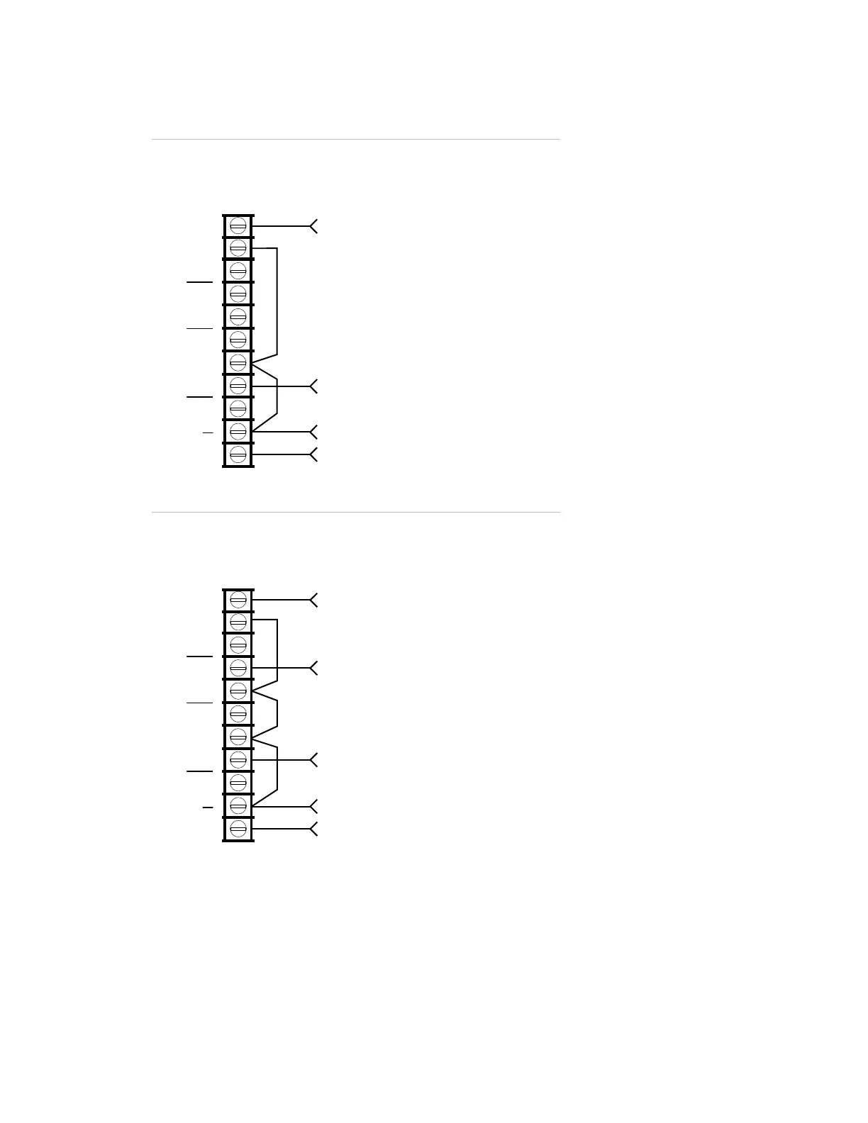
Alarm, supervisory, and trouble transmitted on separate circuits
Note: JP1 on the RPM must be IN.
From ALRM on RPM (brown wire)
From TRBL on RPM (yellow wire)
From COM on RPM (black wire)
From +24 on RPM (red wire)
From SUPV on RPM (orange wire)
ontrol panel
TB3
TRBL
C
NC
SUP
NC
ALM
24VOUT
+
NO
C
NO
+
 Loading...