Chapter 1: System operation
14 EST iO64 and iO500 Technical Reference Manual
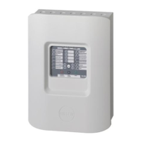
7 Cabinet enclosure: Houses the panel electronics and standby
batteries. In some cases, the batteries may be housed in an
external battery cabinet (BC-3).
8 Operator interface: Includes operator controls, LED indicators,
and control buttons
9 Loop expander card connector (J7): Provides a connection for
the optional loop expander card (only on the 250/500 point
panel)
10 Class A card connector (J2): Provides a connection for the
optional Class A card (only on the 64 point panel)
11 Tie wrap mounts: Used to secure wires and to help maintain
proper separation between power-limited and nonpower-
limited conductors
12 LED expander connector (J6): Provides a connection for the
optional LED expander
13 Standby batteries: Provide secondary/standby power to the
panel electronics in the absence of primary power
 Loading...