Appendix D: Applications
EST iO64 and iO500 Technical Reference Manual 257
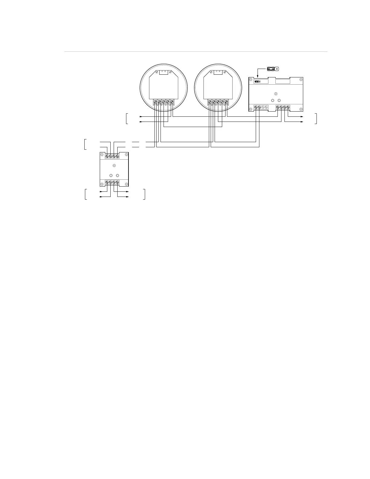
Wiring
12
3
4
56
7
8
RM1
7
8
12
3
4
65
CRR
SIG+
SIG-
DATA- OUT
DATA- IN
DATA+ IN/OUT
SIG+
SIG-
DATA- OUT
DATA- IN
DATA+ IN/OUT
DATA+
DATA-
SLC
DATA+
DATA-
SLC
FIRST
DETECTOR
LAST
DETECTOR
SLC
DATA+
DATA-
DATA+
DATA-
24 VDC+
24 VDC-
UX RISER
NORMAL ACTIVE
-+
+-
SLC
N.C.
JP1: 24 VDC Monitor
Programming
This application requires that you group your detectors into zones
and correlate outputs for each zone. The following instructions are
for Zone 1 but apply for all zones as well.
1. Set the panel’s Event Notification option for Zone.
2. Configure the smoke detectors in Zone 1 as follows:
Device Type: Smoke or Smoke Heat depending on the detectors
used
Message Line 1: SMOKE_<N>, where <N> can be the device
address or other number
Message Line 2: ZONE_01
Coder: 0-0-0-0
Sensitivity: As required
Alt Sensitivity: As required
Pre Alarm: Any value other than None
Alt Pre Alarm: Any value other than None
Verification: N/A
Alt Verification: N/A
Base: Relay/Sounder
Follow Alarm: No
 Loading...