Evolution Series E9000 User Manual
11
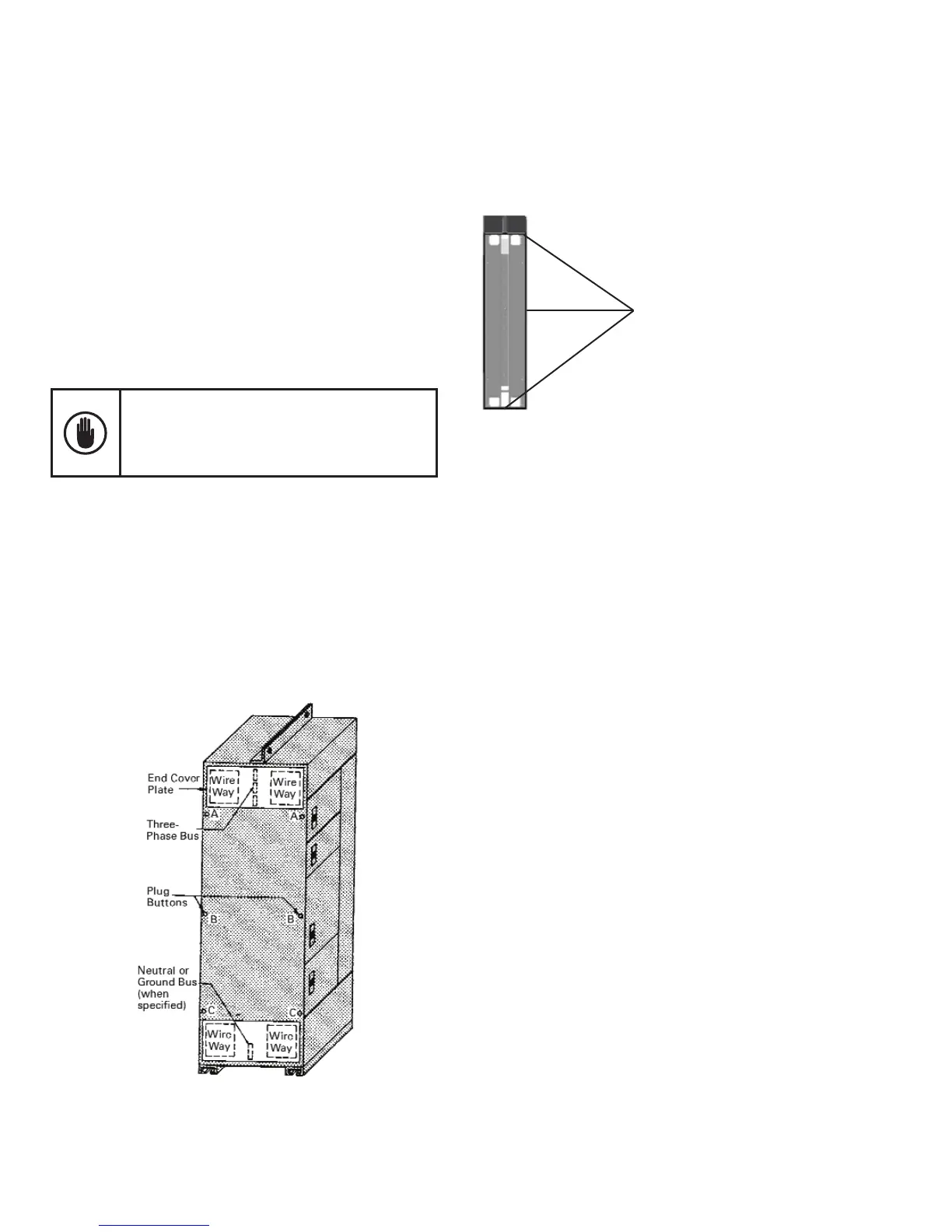
Positioning and Joining Sections
If groups of sections are to be joined together in a nal
lineup, remove the end cover plates and the plug buttons,
from the sides of the sections to be joined. Figure 10
shows the side views, with the end cover plates removed,
for 20-inch-deep sections with 2-inch (50.8 mm) and
4-inch (101.6 mm) bus bars.
Carefully check and remove dirt, dust or bits of packing
material from the interior of all sections. Use a brush,
soft cloth or vacuum cleaner.
Do not use compressed air to clean the equipment
if it contains moisture. Remove all hardware
packages, drawings and other items shipped with
the equipment. Check all nuts, bolts, and electrical
joints for tightness.
All cables entering the bottoms of sections should be
pulled through conduits to a point where they will be
accessible after the equipment is in place. Sections can
be moved to their nal position and properly leveled.
For Arc Resistant plenum-less design, the cables can
enter either through the front or rear aluminum ap on
top of the section.
Figure 10. Side view of a 20-inch-deep section showing the cover
plates, plug bottoms and joining points
For Type 12 and Arc Resistant enclosure, see Figure
10A for proper gasket in between the section splits. For
additional gasket material order part number 245A1888P5.
Gaskets
Figure 10A. Type 12 and Arc Resistant
gasket material between section splits
NEC Work Space
NEC Work Space is dened in Table 110.26(a) Working
Spaces. Included in these clearance requirements is the
step-back distance from the face of the equipment.
Table 110.26(a) provides requirements for clearances
away from the equipment, based on the circuit voltage
to ground, and whether there are grounded or unground-
ed objects in the step-back space, or if there are exposed
live parts across from each other. The voltages to ground
consist of two groups: 0 to 150 and 151 to 600, inclusive.
Remember, where an ungrounded system is utilized, the
voltage to ground will be the greatest voltage between
the given conductor and any other conductor of the
circuit. For example, the voltage to ground for a 480-volt
ungrounded delta system is 480 volts.
See Figure 14 for general working clearance requirements.
Distances are measured from the live parts if the live
parts are exposed, or from the enclosure front if live
parts are enclosed. If any assemblies, such as switch-
boards or motor control centers, are accessible from the
back and expose live parts, the working clearance
dimensions would be required at the rear of the equipment,
as illustrated. Note that for Condition 3, where there is
an enclosure on opposite sides of the working space,
the clearance for only one working space is required.