Evolution Series E9000 User Manual
23
3. Verify (with an insulation-resistance tester) that all
main incoming feeders to the motor control center
are adequately insulated.
4. Close the upstream feeder to energize the motor
control center.
5. Close the main disconnects, if any, at the motor
control center.
6. Close each branch-circuit disconnect or feeder at
the motor control center. For AFM Units, ensure that
all visual indicators are showing “RED” to indicate
“ENGAGED” stab position and “OPEN” shutter position.
7. Operate each motor starter individually to verify satis-
factory operation, including the following parameters:
• Motor rotation
• Pilot light indication
• Electrical interlocking
• Acceleration and sequence timing
Power-factor correction capacitors on
individual motor circuits should be temporarily
disconnected during startup.
8. Adjust instantaneous settings on magnetic-only circuit
breakers and/or fuse sizes and overload heater
selections to achieve proper motor and branch circuit
protection. (See NEC Article 430.52.) Since the
adjustable trip setting on magnetic-only circuit
breakers is factory set at the minimum trip position,
nuisance tripping may occur on initial motor starting.
Increase the trip setting in increments until tripping
no longer occurs during motor starting. Do not exceed
the maximum trip settings given in overload relay
tables in this publication. All adjustable overloads
are also factory set at minimum. Check motor
name-plate data and set overloads accordingly.
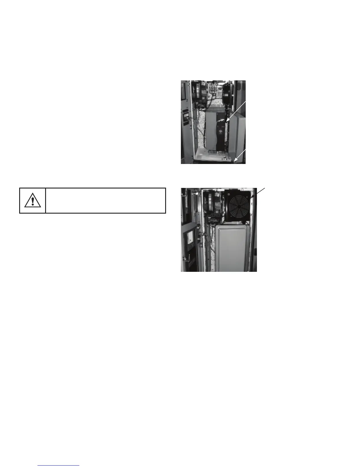
Door Closing Procedure of Pilot Device Bracket,
Extension Bubble Door for Some GP/FP Drives
E9000 MCC units
Variable
Frequency
Drive
Extension
Bubble
Figure 35. Door, pilot device bracket and extension bubble
in open position
PD Bracket
Figure 36. Partially close the pilot device bracket
and extension bubble as shown