Evolution Series E9000 User Manual
5
Bus Splicing
Main, neutral and ground bus splice bars (with all
associatedhardware) are furnished, as necessary, to
join sections together. They are located in the rst
section tothe right of the joint. See Figures 13, 14 and
15 for approximatedimensions for main, neutral, and
ground bus.
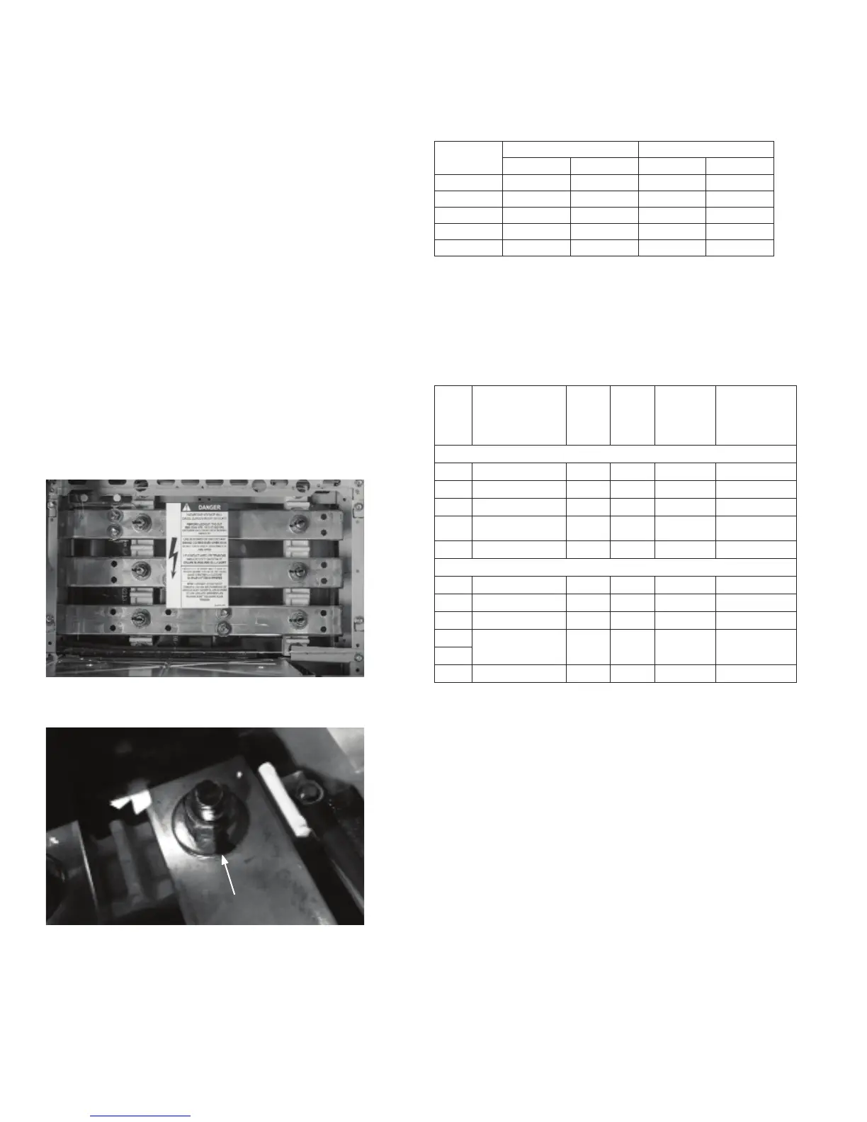
Remove the top Lexan barrier, as shown in Figure 11 and
Figure 12, to access the main bus. Refer to instruction
drawings in splice kit. See Table 2.
Arc Resistant design has metallic barrier in addition to
the Lexan barrier which also must be removed to
access the main bus. Arc Resistant shipping splits will
arrive with end caps. When bus splicing, please remove
these end caps to make connection, only the furthest
most left and right end caps shall remain.
Figure 12. Horizontal bus barrier mounting slot and screw
Figure 11. Horizontal bus with Lexan barrier
Loosen screw, lift and
pull barrier forward
Table 1. Torque values for various bolt sizes and joint types
Bolt Size
Copper Joints Aluminum Joints
lb-ft N-m lb-ft N-m
5/16-18 5–9 7–12 6.5–9 9–12
3/8-16 12–16 16–22 10–15 14–20
1/2-13 30–39 41–53 25–35 34–47
5/8-11 65–80 88–108 35–45 47–61
3/4-10 125–150 169–203 50–75 68–102
Note: When assembling or connecting to aluminum bus, apply a suitable joint
compound between the contacting surfaces.
Bus Splice Kits
Table 2. Bus Splice Kits
Splicing From / To E9000/E9000
Amps
Main Bus Splice
Assembly Kit
Bars/
Phase
Copper
Size
(in.)
(thick x
width)
SC Rating
600V Max.
(sym.
amps)
Splice
Instruction
Drawing*
Standard Splicing
600 110C1735G1SM 1 1/4 x 2 65K 110C1258TG1
800 110C1735G4SM 1 3/8 x 2 65K 110C1256TG1
1200 110C1735G7SM 1 1/2 x 2 100K 110C1253TG1
1600/
2000
110C1735G12SM 2 1/2 x 2 100K 110C1263TG1
2500 110C1735G13SM 2 1/2 x 2 100K 110C1785TG1
N3R and Spacer Shells
600 110C1735G14SM 1 1/4 x 2 65K 110C1258TG1
800 110C1735G15SM 1 3/8 x 2 65K 110C1256TG1
1200 110C1735G16SM 1 1/2 x 2 100K 110C1253TG1
1600/
110C1735G17SM 2 1/2 x 2 100K 110C1263TG1
2000
2500 110C1735G13SM 2 1/2 x 2 100K 110C1263TG1
*Included in kits
Note: Standard plating is tin. Refer to factory for alternate plating.