43
2. Starting at the bottom, attach the inside gasket
lip to the front tub inside lip.
3. Ensure gasket drain holes remain aligned with
the front tub drain holes.
4. Attach the outside gasket clamp lip to the outside
lip of the front tub.
5. Reinstall the inside gasket clamp with the head of
the clamp adjustment screw pointed up and posi-
tioned at approximately the 3 o’clock position.
6. Tighten the inside clamp snugly, do not deform
the clamp by over tightening.
7. Reinstall tub lamp and hoses.
8. Attach the front panel gasket lip to the front
panel lip and reinstall clamp.
9. Check for water leaks.
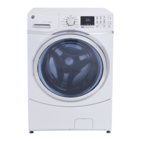
Tub Lamp
Operating Voltage: 3.1 VDC
Resistance: N/A
Location: See Tub Lamp Location on page 34.
The tub lamp is an LED light. It is energized as soon
as the door is opened or when the Light button
is pressed. The lamp fades in intensity from on to
off or off to on, transition time is approximately 1
second. A software timer limits the on time of the
lamp to a maximum of 5 minutes. Pressing the Light
button will reenergize the lamp and restart the 5
timer.
Note: Tub lamp leads cannot be removed from the
lamp. The lamp harness is part of the tub lamp.
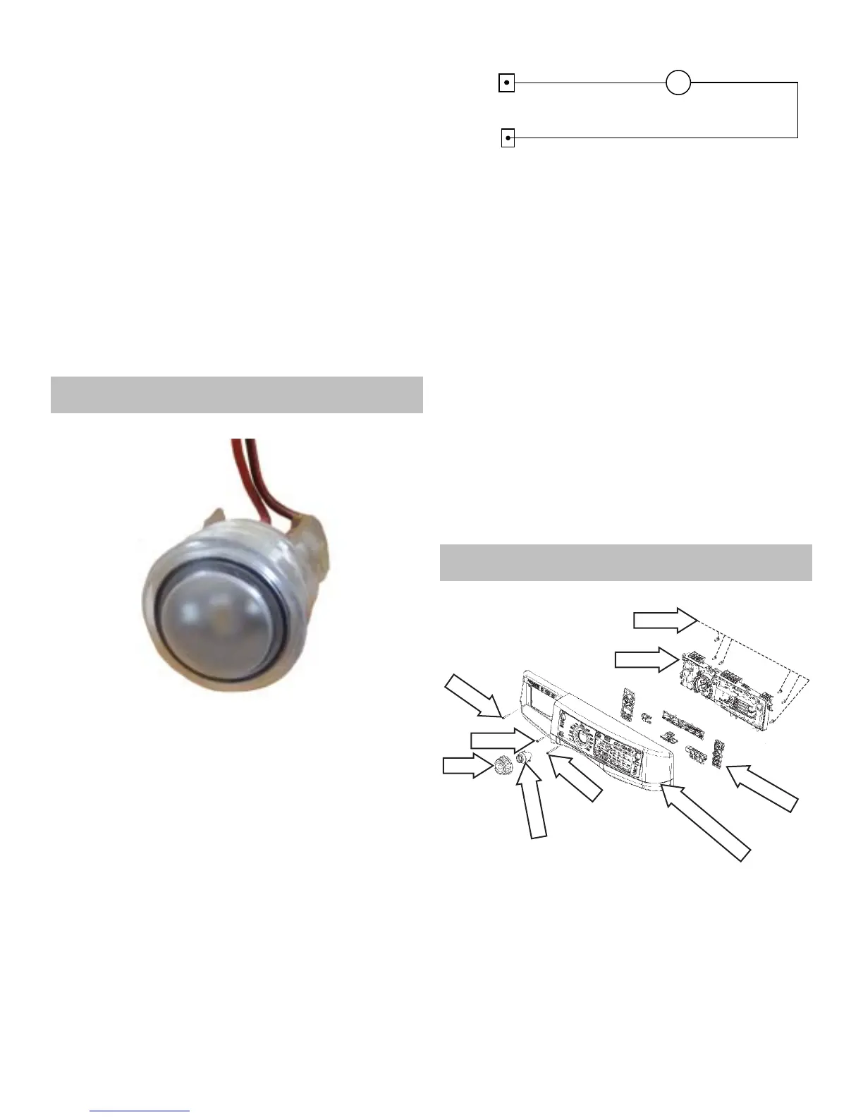
Tub Lamp Strip Circuit
IMC J702-1
IMC J101-4
3.1 VDC
DC GND
L
Tub Lamp Diagnostics
1. Press the Light button to energize the lamp.
2. Check for 3.1 VDC between IMC J204 pins 1 & 2.
• If 3.1 VDC is present replace the tub lamp
• If 3.1 VDC is not present replace the IMC
board.
Tub Lamp Removal
1. Disconnect power to the unit.
2. Remove the front clamp of the tub gasket and
pull the gasket down to access the tub lamp.
(See Tub Gasket Removal)
3. Carefully pull the tub lamp out of the top of the
tub gasket.
Note: When reinstalling the tub lamp, ensure the tub
lamp bottoms out in the gasket.
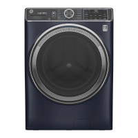
Control Panel
Control Panel Components
#2 Phillips
T-20 Torx
Knob Retainer
Knob
5/16” Hex
UI Board
Button Trees
#2 Phillips
Control Panel
Location: See Control Panel Location on page 34.
The control panel is a plastic housing with graphics.
The button trees, knob, knob retainer and UI board
must be obtained separately.