EasyManuals Logo

GE GL 310 F3/4031 P/VR User Manual

GE GL 310 F3/4031 P/VR
140 pages
To Next Page IconTo Next Page
To Previous Page IconTo Previous Page
Page #36 background imageLoading...
Page #36 background image
INSTALLATION
36 OI 248 (EN) REV6 /REV5
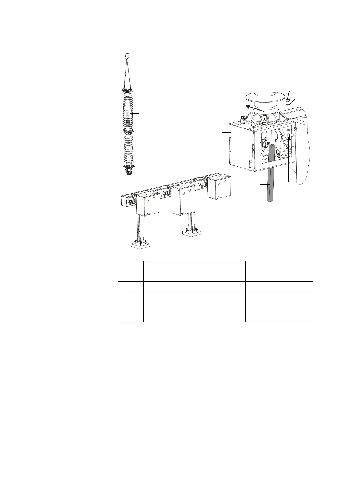
The opening springs are located in the crankcases of the pole co-
lumns. The opening springs fix the pole columns in open position.
All other installation steps are based on this open position of the
pole columns.
1 Pole column 1x
2 Base frame 1x
3 Washer, 16 A2 8x
4 Hexagon bolt, M16x55 8.8 TZN 4x
5 Hexagon nut, M16 A2-70 4x
6 Tire lever Not supplied
1
2
5
3
4
6
A
C
B
BA-P-F3-SCHALTER / BA-P-SCHALTER-1

Table of Contents

Questions and Answers:

Question and Answer IconNeed help?

Do you have a question about the GE GL 310 F3/4031 P/VR and is the answer not in the manual?

GE GL 310 F3/4031 P/VR Specifications

General IconGeneral
BrandGE
ModelGL 310 F3/4031 P/VR
CategoryCircuit breakers
LanguageEnglish

Related product manuals