INSTALLATION
REV6 /REV5 OI 248 (EN) 39
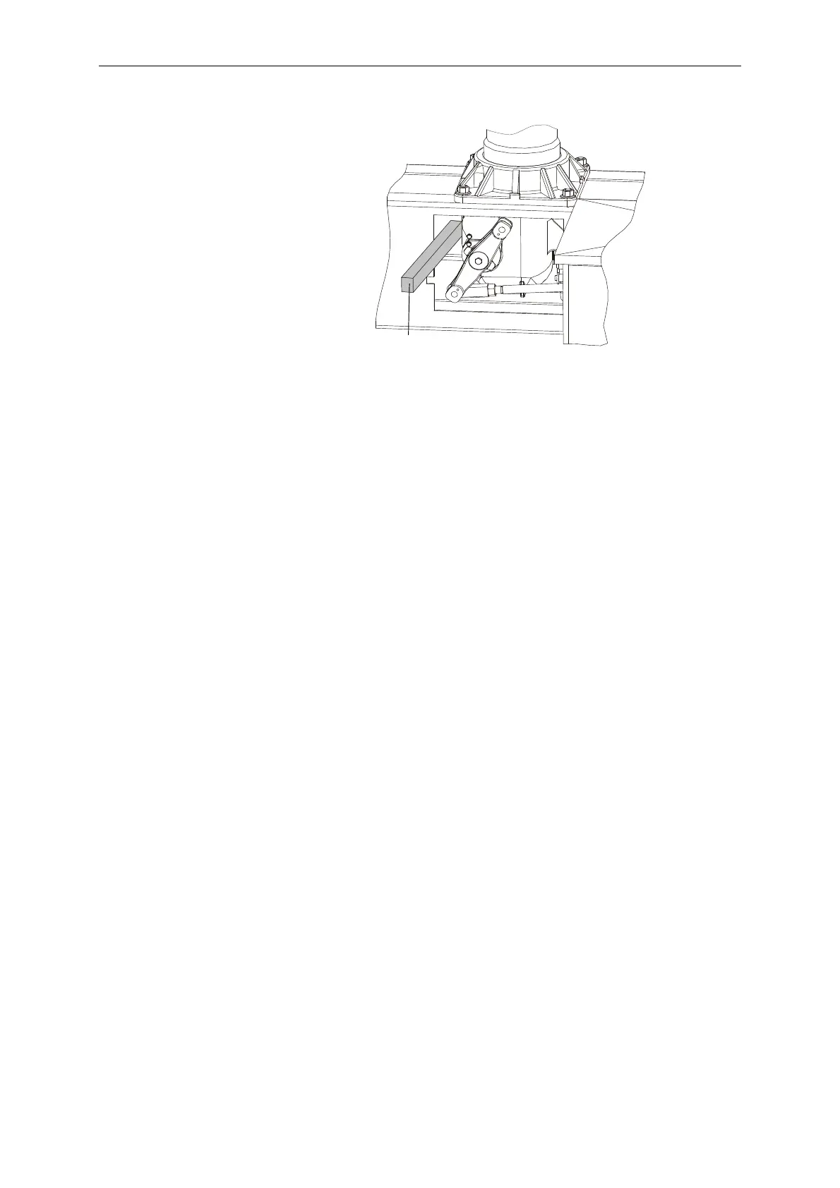
• Brace the tire lever (16) against the side of the base frame or
support and push the pole column until the holes in lever (6) and
the drive rod (5) are aligned. Lubricate the flanged coupling pin
(14) as per L2. The flanged coupling pin (14) must slide in easily.
• Remove the tire lever and flanged coupling pin (14) again, and
insert the sleeve (15) into the lever (6)
• Connect the lever (6) and drive rod (5) to the flanged coupling pin
(14) and the sleeve (15)
• Apply locking adhesive S1 to the screw (13).
• Lock the flanged coupling pin (14) using the locking sleeve (11),
washer (12) and screw (13). Tighten to a torque of 7Nm.
• Complete the connection between pole column and the base
frame by tightening the four pole column mounting bolts to a
torque of 146Nm.

 Loading...


