Home
GE
Washer
GTWN8250DWS
Page 97 (Drive Motor Diagnostics)
GE GTWN8250DWS - Drive Motor Diagnostics
108 pages
Manual
To Next Page
To Next Page
To Previous Page
To Previous Page
Loading...
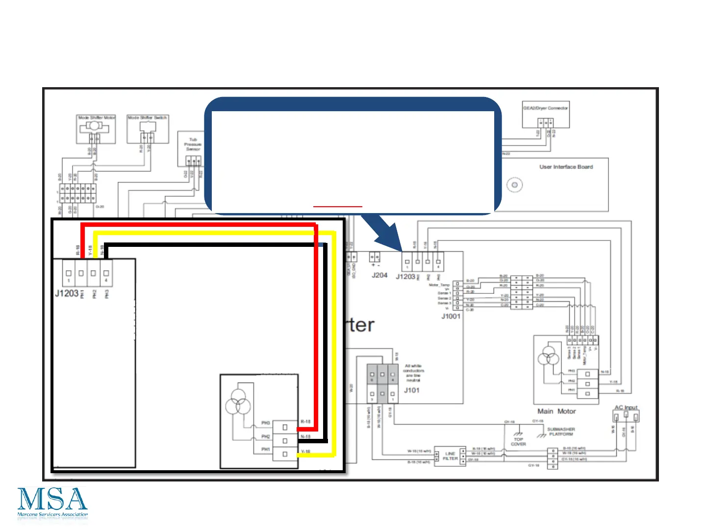
Checking fr
om one of the 3 phase wires,
RED
,
YELLO
W
or
BLUE
on connecter
J1203 to any of the other
wir
es on the
same connecter
, the
r
esist
ance should be
appro
ximately
18 ohm
Diagnos
tics Fr
om The
Boar
d
Drive Moto
r
97
96
98
Table of Contents
Main Page
Laundry
2
Important Safety Notice
4
Reconnect All Grounding Devices
4
2012 Clothes Care Nomenclature Washer
5
HE Detergent
6
Location
7
Warranty
8
Distinguishing Characteristics
10
Dispenser Configuration
10
Dispenser Configuration Low End
11
Dispenser Configuration MID Grade
12
Dispenser Configuration High End
13
Bulk Dispense
13
Backsplash Assembly
14
Removal and Accessing Boards
14
Lid Assembly
16
Re-Installing the Lid
19
Hinges
20
Top Cover Removal
21
Remove 2 Screws
21
Basket and Tub
23
Basket and Tub Removal
24
Components Overview
28
Water Valves
29
Removing the Water Valve
33
Reinstalling the Water Valve
37
Closing Click Clamps with Click Pliers
38
Opening Click Clamps with Click Pliers
39
Reinstall Water Valve to the Top Cover
45
Reinstalling the Fill Funnel
46
Lid Lock Assembly
48
Bulk Dispenser Tanks
49
Pressure Sensor
54
Location and Removal
54
Tub Water Level / Hz Conversion
57
Pressure Sensors for Bulk Tanks
58
Bottom of Subwasher
60
Bulk Dispenser Pressure Sensor Location
60
Component Locations
60
Water Pumps
61
To Remove Either Pump
62
To Reinstall Either Pump
62
Drive System
63
Drive System Rotor Removal
64
Stator
65
To Remove Stator
65
RPS Switch Hall Sensor
66
Hall Sensor Is Easy to Remove
66
Mode Shifter
67
Mode Shifter Assembly
68
Platform Assembly Removal
69
Platform Assembly Installation
72
Heater Assembly
74
Thermistor
75
Schematic
76
Common Diagram to All Models
76
Wiring Diagram
76
Washer IMC Board
76
Strip Circuits Not Common to All Models – Water Valves
77
Water Valve Assembly
77
Strip Circuits Not Common to All Models – Bulk Tank Sensors
80
Strip Circuits Not Common to All Models
81
Heater Circuit
81
Strip Circuits Not Common to All Models – Tub Light
82
Strip Circuits Not Common to All Models – Recirculation Pump
83
UI Logic Board and RJ45 Board
84
IMC/Inverter Board
85
Diagnostics from the Board
86
AC Voltage into the Board – Not Powering up
86
Recirculation Pump
87
Drain Pump
88
Mode Shifter Motor Resistance
89
Mode Shifter Position Switch
90
Thermistor Resistance
91
Lid Lock Motor
92
Lid Switch
93
Lid Lock Position Locked/Unlocked
94
Tub Light
95
UI Logic Board Voltage
96
Drive Motor
97
Testing the Rps/Hall Sensor
98
Heater and Continuity Circuit
99
Service Mode
100
How to Enter the Service Mode and Navigate
100
Tests
101
Lid and LED Check
101
How Water Valve Check
101
Cold Water Valve Check
101
Spin
102
Drain Pump Check
102
Recirculation Pump Check
102
Heater Check
102
Lid Lock
103
Driver Communication Test
103
Error Codes
103
Clear Error Codes
103
Fault Codes
104
Frequently Asked Questions
107
What Is the Difference between Heavy and Light Settings?
107
Which Cycle Is Best for Heavily Soiled Items?
107
How Can I Reduce Linting?
107
Related product manuals
GE GTWN4250M
24 pages
GE GTWN5250D
2 pages
GE GTWN4250DWS
24 pages
GE GTWN2800DWW
24 pages
GE GTWN7450DWW
108 pages
GE GTWN4950L0WS
24 pages
GE GTWN3000M2WS
6 pages
GE GTWN3000M1WS
6 pages