GEK-45375
f)
.UEllL
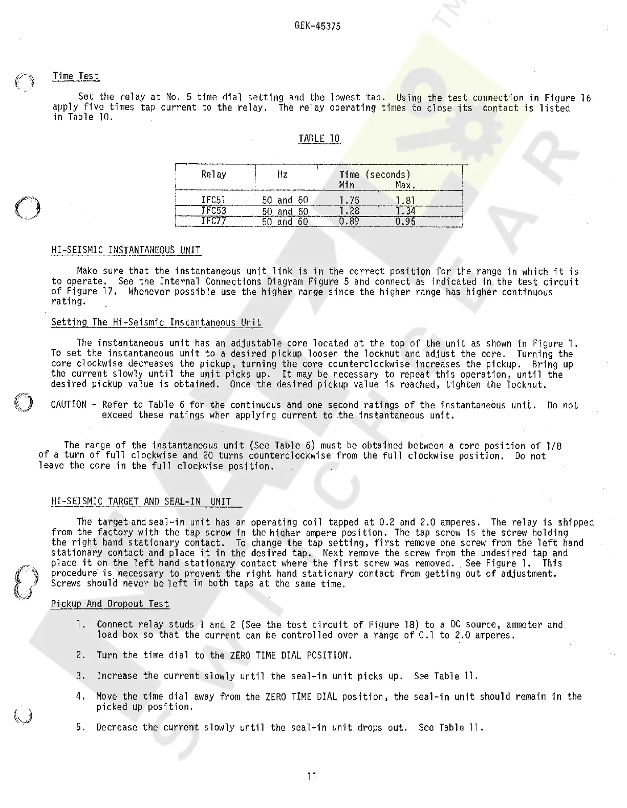
Test
()
Set the relay
at
No.
5 time dial
setting
and
the lowest tap.
Using
the
test
connection in Figure
16
apply five times tap current to the relay.
The
relay operating times to close
its
contact
is
listed
in Table 10.
,--·
;
Relay
r
IFC51
IFC53
IFC77
HI-SEISMIC
INSTANTANEOUS
UNIT
Hz
--.---:N~~-
(seconds)
-T
Min.
Max.
'
50
and
60
50
and
60
·50
and
_60·
~------·--,
1.75
1.81
i
1 . 28,__
__
·
-'-'1.'-"3-'-4-
0.
89
0.95
Make
sure
that
the instantaneous unit
link
is
in the
correct
position for the range in
which
it
is
to operate.
See
the Internal Connections
Diagram
Figure 5
and
connect
as
indicated
in
the
test
circuit
of Figure 17.
Whenever
poss i b 1 e
use
the higher range s i
nee
the higher range
has
higher continuous
rating.
Setting
The
Hi-Seismic lnstantanepus Unit
The
instantaneous unit
has
an
adjustable core located
at
the top of the unH
as
shown
in Figure 1.
To
set
the instantaneous
unit
to a desired pickup loosen the locknut
and
adjust the core. Turning the
core clockwise decreases the pickup, turning the core counterclockwise increases the pickup. Bring
up
the current slowly
until
the unit picks
up.
It
may
be
necessary to repeat
this
operation,
until
the
desired pickup value
is
obtained.
Once
the desired pickup value
is
reached, tighten the locknut.
()
CAUTION
- Refer to Table 6 for the continuous
and
one
second
ratings
of
the instantaneous
unit.
Do
not
exceed these ratings
when
applying current to
the
instantaneous
unit.
The
range
of
the instantaneous
unit
(See Table
6)
must
be
obtained
between
a core position
of
1/8
of a turn
of
full
clockwise
and
20
turns counterclockwise
from
the
full
c"lockwise
position.
Do
not
leave the core in the
full
clockwise
position.
ll.!::SEISMIC
TARGET
AND
SEAL-IN
UNIT
The
target
and
seal-in
unit
has
an
operating coil tapped
at
0.2
and
2.0 amperes.
The
relay
is
shipped
from
the factory with the tap screw in the higher
ampere
position.
The
tap
screw
is
the screw holding
the
right
hand
stationary
contact.
To
change
the tap
setting,
first
remove
one
screw
from
the
left
hand
stationary
contact
and
place
it
in the desired tap.
Next
remove
the
screw
from
the undesired tap
and
place
it
on
the
left
hand
stationary
contact
where
the
first
screw
was
removed.
See
Figure 1. This
procedure
is
necessary to prevent the
right
hand
stationary
contact
from
getting out of adjustment.
Screws
should never
be
left
in both taps
at
the
same
time.
£.i_ckup
And
Dropout Test
1. Connect relay studs 1
and
2
(See
the
test
circuit
of Figure
18)
to a
DC
source,
ammeter
and
load
box
so
that
the current
can
be
controlled over a range of 0.1 to 2.0 amperes.
2.
Turn
the time dial to the
ZERO
TIME
DIAL
POSITION.
3. Increase the current slowly until the
seal-in
unit picks
up.
See
Table 11.
4.
Move
the
t·ime
dial
away
from
the
ZERO
TIME
DIAL
position,
the
seal-in
unit should remain in the
picked
up
position.
5. Decrease the current slowly until the sea·l-in unit drops out.
See
Table
ll.
11
Courtesy of NationalSwitchgear.com
 Loading...