()
GEK-45375
HI-SE
I
SM!
C
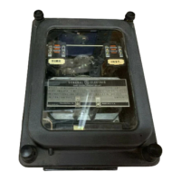
INSTANTANEOUS
UNIT
The
instantaneous un'it
has
a
25
to l range
1vith
a tapped
coil.
There are high
and
low
ranges,
selected
by
means
of
a
link
located
on
the top
of
the support
structure.
See
Fiqure
l.
The
time-
current
curve
for
the instantaneous unit
is
shown
in
Figure 14.
··
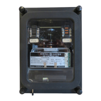
HI-SEISMIC
TARGET
AND
SEAL-IN
UNIT
The
target
and
seal-in
unit
has
two
tap
selections
located
on
the
front
of
the
unit.
see Figure
l.
REC_fJ.\l.!l!_(i_,_Jl.ANDLING
AND
STOR_l\.GE
These
relays,
when
not included
as
a
part
of
a control panel, l'rill
be
shipped
·in
cartons designed
to
protect
them
against
damage.
Immediately
upon
receipt
of
a
relay,
examine
it
for
any
damage
sustained
·in
transit.
If
injury
or
damage
resulting
from
rough
handling
is
evident,
file
a
damage
claim
at
once
with the
transportation
company
and
promptly notify the
nearest
General Electr'ic
Apparatus Sales Office.
Reasonable care should
be
exercised in unpacking the
relay
in order
that
none
of
the
parts
are
injured
or
the adjustments disturbed.
If
the relays are not to
be
installed
immediately, they should
be
stored in
their
original
cartons in a place
that
is
free
from
moisture, dust
and
metallic
chips. Foreign matter
collected
on
the
outside
may
find
its
way
inside
when
the cover
is
removed
and
cause trouble in the operation of
the
relay.
ACCEPTAN_c:E
TESTS_
Immediately
upon
receipt
of
the
relay
an
INSPECTION
AND
ACCEPTANCE
TEST
sh.ould
be
made
to ·insure
that
no
damage
has
been
sustained in shipment
and
that
the
relay
ca'librations
have
not
been
disturbed.
If
the examination
or
test
ind·icates
that
readjustment
is
necessary,
refer
to the section
on
SERVICING.
These
tests
may
be
performed
as
part
of
the
installation
or
acceptance
tests
at
the
discretion
of the user.
Since
most
operating companies use
different
procedures for acceptance
and
installation
tests,
the following
section
includes
all
applicable
tests
that
may
be
performed
on
these
relays.
VISUAL
INSPECTION
Check
the nameplate to ·insure
that
the
mode'I
number
and
ratino
of
the relay agree •1ith the
requisition.
Remove
the
relay
from
its
case
and
check
that
there
are
no
broken or cracked
parts
or
any
other
signs
of
physical
damage.
MECHANICAL
INSPECTION
1. There should
be
no
noticeable
friction
when
the disk
is
rotated
slowly clockwise.
The
disk
should return
by
itself
to
its
rest
position.
2.
Make
sure the contra l spring
is
not deformed nor
its
convo
l uti ans tangled or touching.
3.
The
armature
and
contacts
of
the
seal-in
unit
as
well as the armature
and
contacts
of
the
instantaneous un'it should
move
freely
when
operated
by
hand, there should
be
at
least
1/64"
wipe
on
the
seal-in
and
the instantaneous
contacts.
4.
The
targets
in the sea
1-i
n
unit
and
in the instantaneous
unit
must
come
into
view
and
latch
when
the armatures are operated
by
hand
and
should unlatch
when
the
target
release
button
is
operated.
5.
Make
sure
that
the brushes
and
shorting bars agree •rith the ·internal connections d·iagram.
6.
CAUTION:
Should there
be
a
need
to
tighten
any
screws,
DO
NOT
OVER
TIGHTEN
to prevent
stripping.
9
Courtesy of NationalSwitchgear.com
 Loading...