GEK-45375
f.)
5
_ Since the instantaneous unit co'il
is
in·
series
with the time overcurrent
unit
co'il see Tables 3 4
and
6 to determine the current l·imitinq element
for
both continuous
and
short time
ratings.
' '
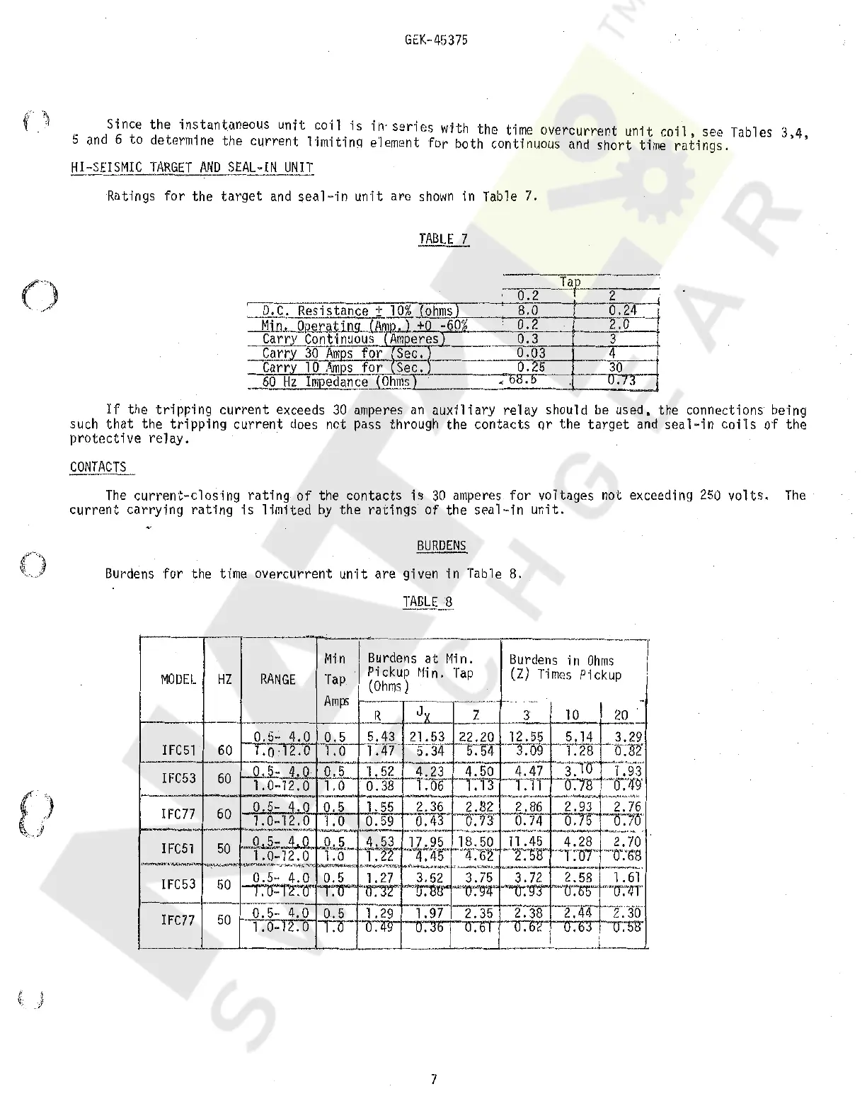
)il:SEJSMIL_JARGET
AN_ll
SEAL-IN
_UNIT
Ratings for the
target
and
seal-in
un"it
are
shown
in Table 7.
JABLE
7
8.0
.
--1
0.24
0.2
2.o
o::r--
--3-
-
0.03
4
--
o.25
30
<
871>
u
·'
·'
If
the
tripping
current
exceeds
30
amperes
an
aux'i"liary
re"lay
should
be
used, the connections being
such
that
the
tripping
current
does
not pass through the contacts
or
the
target
and
seal-in
coils
of the
protective
relay.
The
current-closing
rating
of
the contacts
is
30
amperes
for voltages not exceeding
250
volts.
The
current
carrying
rating
is
limited
by
the
ratings
of the seal
·in
unit.
BURDENS
Burdens
for the time overcurrent
unit
are
given in Table 8.
MODEL
HZ
--r~-·-··~-----~----------·---------·--r
RANGE
Min
Tap
Burdens
at
Min.
Pickup
Min.
Tap
(Ohms)
7
Burdens
in
Ohms
(Z)
Times
Pickup
I
I
Courtesy of NationalSwitchgear.com
 Loading...