(
(
)
'
,_
..
_,,,
GEK-45375
TIME
OVERCURRENT
RELAYS
TYPES
IFC
51A
and
51B
IFC
53A
and
538
IFC
77A
and
778
jlESc_RIPT~ON
The
type I
FC
re 1 ays covered
by
these
instructions
a re extended range,
single
phase,
ti
me
overcurrent
relays.
The
various
time-current
characteristics
available
are
as
follov.1s:
IFC51
A,
I
FC51B
!FC53A,
I
FC53B
I
FC77
A,
I
FC77B
Inverse time
Very
inverse
time
Extremely
inverse
time
The
IFC51B,
538
and
77B
relays
also
include a hinged-armature instantaneous
overcurrent
unit
which
provides
instantaneous
tripping
at
high
current
levels.
The
instantaneous
unit
is
not included in the
IFC51A,
53A
or
77A
relays.
Both
the time
overcurrent
unit
and
the instantaneous
overcurrent
unit
are
described
in
detail
in
the
section
on
CONSTRUCTION.
F.ach
relay
is
equipped with a dual
rated
target
and
seal-in
unit.
When
semi
flush
mounted
on
a
suitable
panel,
these
relays
have a high seismic
capability
including
both the
tar~et
seal-in
unit
and
the instantaneous
overcurrent
unit
when
it
is
supplied.
Also, these
relays
are recognized under the
Components
Program
of
Underwriters
Laboratories,
Inc.
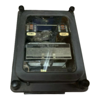
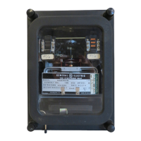
The
relay
is
mounted in a
size
Cl
drawout case
of
molded
construction.
The
outline
and
panel
drilling
are
shown
in Figures
23
and
24.
The
relay
internal
connections are
shown
in
Fi~ure
4
for
the
IFC51A,
IFC53A
and
IFC77A,
and
in
Figure 5
for
the
IFC51B,
IFC538
and
IFC778.
AP£)-
I
CATION
Time
overcurrent
relays
are used
extensively
for
the
protection
of
utility
and
industrial
power
dis-
tribution
systems and
frequently
for
over.load backup
protection
at
other
locations.
The
EXTREMELY
INVERSE
time
characteristics,
Figure 8
and
22,
of
the
IFC77A
and
IFC778
relays
are designed
primarily
for
use where
they
are
required
to coordinate
rather
closely
with
power
fuses,
distribution
cutouts
and
reclosers.
They
also
provide
maximum
tolerance
to allow
for
cold load pickup. This
is
the
result
of
an
extended
service
outage which
results
in a heavy accumu'lation of loads
of
automatically
contro'lled devices such as
refri~e
rators,
vrnter
heaters,
water
pumps,
oil
burners,
etc.
Such
load accumulations
often
produce inrush
cur-
rents
considerably in excess of feeder
full
load
current
for
a
short
time
after
the feeder
is
energized.
The
EXTREMELY
INVERSE
time
characteristic
often
permits successful pickup
of
these loads
and
at
the
same
time provides adequate
fault
protection.
The
VERY
INVERSE
time
characteristics,
Figure 7
and
2·1,
of
the
IFC53A
and
IFC538
relays
are
likely
to provide
faster
overall
protection
in
applications
where the
available
fault
current
magnitude remains
fairly
constant
due
to a
relatively
constant
generating
capacity.
The
variation
in the magnitude
of
fau'lt
current
thru
the
relay
is
therefore
mainly dependent
upon
the 'location
of
the
fault
with
respect
to the
re-
lay.
The
INVERSE
time
overcurrent
characteristics,
Figure 6
and
20, of .the
IFC51A
and
IFC51B
relays
tend
to
make
the
relay
operating
time
less
dependent
upon
the magnitude
of
the
fault
current
than in the case of
VERY
INVERSE
and
EXTREMELY
INVERSE
devices. For
this
reason,
INVERSE
type
relays
are 'likely to provide
faster
overall
protection
in
applications
where the
available
fault
current
magnitudes vary
significantly
as
a
result
of
frequent
changes in the source impedance
due
to system loading
and
switching.
The
usual
application
of
these
relays
requires
three
relays
for
multiphase
fault
protection,
one
per
phase,
and
a
separate
relay
residually
connected
for
single-phase-to-ground
faults.
Ty
pi
cal
external
connections
for
this
application
are
shown
in Figure 9.
Use
of
a
separate
ground relay
is
advantageous
because
it
can
be
set
to provide
more
sensitive
protection
against
ground
faults.
In
the
application
of
these
relays
with downstream automatic
reclosing
devices, the
relay
reset
time
should
be
considered. This
is
the time required
for
the
relay
to
go
from
the
contacts
fully
closed
posit-
ion to the
fully
open
position
when
set
at
the
number
10
time
dial.
At
lower time
dial
settings
the
reset
times
are
proportionately
lower.
The
reset
time
of
all
VERY
INVERSE
and
EXTREMELY
INVERSE
relays
is
appro-
ximately
60
seconds.
The
reset
time
of
all
INVERSE
re.lays covered
by
these
instructions
is
approximately
7 seconds.
'1.'hese
instructions
do
not
purport
to
cover
all
details
or
variations
in
equipment
nor
to
provide
for
every
possible
contingency
to
be
met
in
connection
with
installation,
operation
or
maintenance.
Shoul.d
further
information
be
desired
or
should
particular
problems
arise
which
are
not
covered
sufficiently
.for
the
purchaser's
purposes,
the
matter
should
be
referred
to
the
General
Electric
Company.
To
the
extent
required
the
products
descr.ibed
herein
meet
applicable
ANSI,
.TEEE
and
NEMA
standards;
but
no
such
assurance
is
given
with
respect
to
local
codes
and
ordinances
because
they
vary
greatly.
3
Courtesy of NationalSwitchgear.com
 Loading...